
Data Sheet for Product


MVL661… Modulating Refrigerant Valves Technical Instructions
Valves with Magnetic Actuator Document Number 155-400
May 11, 2016
Page 3
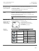
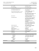
Operator controls and
indicators in the
electronics housing
1 Connection terminals
2 LED for indication of operating state
3 Minimal stroke setting potentiometer Rv
4 Auto-calibration
5 DIP switches for mode control
DIP Switch
Configurations
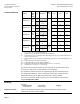
Table 1. DIP Switch Configurations.
Switch
Function
ON/OFF
Description
Positioning signal Y
ON
Current (mA)
OFF
Voltage (V)
1)
Positioning range Y and U
ON
2 to 10 Vdc, 4 to 20 mA
OFF
0 to 10 Vdc, 0 to 20 mA
1)
Position feedback U
ON
Current (mA)
OFF
Voltage (V)
1)
Nominal flow rate C
V
(k
vs
)
ON
63%
OFF
100%
1)
1)
Factory setting
Technical/
Mechanical Design
Features and Benefits
Four selectable control signals.
DIP switch to reduce the C
V
(k
vs
) value to 63% of the nominal value.
Potentiometer for adjustment of minimum stroke for suction throttle applications.
Automatic stroke calibration.
Forced control input for “Valve closed” or “Valve fully open”.
LED for indicating the operating state.
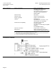
Control
The MVL661… Series valve can be driven by Siemens or third-party controllers that
deliver a 0 to 10 Vdc/2 to10 Vdc, 0 to 20 mA/4 to 20 mA control signal.
For optimum control performance, Siemens Industry, Inc. recommends a 4-wire
connection between controller and valve.
The valve stroke is proportional to the control signal.
CAUTION:
You must use a four-wire connection with Vdc power supply.
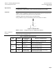
Spring return action
If the positioning signal is interrupted, or in the event of a power failure, the valve’s return
spring will automatically close control path A AB.