
Data Sheet for Product

Technical Instructions MVL661… Modulating Refrigerant Valves
Document Number 155-400 Valves with Magnetic Actuator
May 11, 2016
Page 6
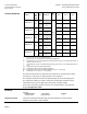
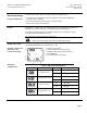
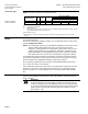
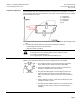
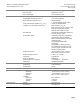
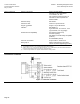
Connection type
4-wire connection
3-wire connection
NOTE: Four-wire connections are always preferred.
Product Number
(VA)
(W)
(A)
Wire Gauge (AWG)
14
12
10
Max. Cable Length Ft (m)
MVL661..-..
22
12
1.6 to 4A
213 (65)
361 (110)
525 (160)
MVL661..-..
22
12
1.6 to 4A
65 (20)
115 (35)
164 (50)
S
NA
= Nominal apparent power for selecting the transformer.
P
med
= Typical power consumption.
I
F
= Required slow fuse.
L = Max. cable length; with 4-wire connections, the max. permissible length of the separate 14 AWG (1.5 mm
2
)
copper positioning signal wire is 656 ft (200 m).
1)
All information at 24 Vac.
2) With 10 AWG (4 mm
2
) electrical wiring reduce wiring cross-section for connection inside valve to 12 AWG
(2.5 mm
2)
.
Sizing
For straightforward valve sizing, see Application Examples, beginning on page 12 for
the relevant application.
For accurate valve sizing, Siemens Industry, Inc. recommends using the valve sizing
software Refrigeration VASP.
NOTE: The refrigeration capacity Q
0
is calculated by multiplying the mass flow by the
specific enthalpy differential found in the h, log p-chart for the relevant
refrigerant. To help determine the refrigeration capacity more easily, see the
selection chart provided for each application. With direct or indirect hot-gas
bypass applications, the enthalpy differential of Q
c
(the condenser capacity)
must also be taken into account when calculating the refrigeration capacity.
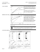
If the evaporating and/or condensing temperatures are between the values shown in
the tables, the refrigeration capacity can be determined with reasonable accuracy by
linear interpolation. See Application Examples, beginning on page 12.
At the operating conditions given in the tables, the permissible differential pressure
p
max
across the valve is not considered.
If the evaporating temperature is raised by 1K, the refrigeration capacity increases by
about 3%. If, by contrast, sub-cooling is increased by 1K, the refrigeration capacity
increases by about 1 to 2% (this applies only to sub-cooling down to approximately
8K).
Engineering Notes
Depending on the application, additional installation instructions may need to be
observed and appropriate safety devices (such as pressostats, full motor protection,
and so on) fitted.
WARNING:
To prevent damage to the seal inside the valve insert, the plant must be
vented on the low-pressure side following a pressure test (valve port AB),
or the valve must be fully open during the pressure test and during venting
(power supply connected and positioning signal at maximum or forced
opening by G ZC).