
Data Sheet for Product


MVL661… Modulating Refrigerant Valves Technical Instructions
Valves with Magnetic Actuator Document Number 155-400
May 11, 2016
Page 11
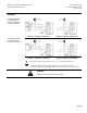
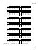
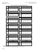
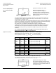
Connection
Diagrams
Terminal assignment
for controller with
four-wire connection
(preferred method)
Figure 3. Common Transformer.
Figure 4. Separate Transformer.
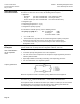
Terminal assignment
for controller with
three-wire connection
Figure 5. Common Transformer.
Figure 6. Separate Transformer.
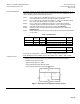
U
Valve position indication (only if required). 0 to 10 Vdc → 0 to 100% volumetric flow 100.
Twisted pairs. If the 24 Vac power supply and the 0 to 10 Vdc/2 to 10 Vdc, 0 to 20 mA/
4 to 20 mA) positioning signal are routed separately, the 24 Vac line does not need to be twisted.
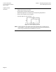
WARNING:
Piping must be connected to potential earth.