
Data Sheet for Product
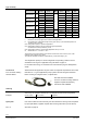
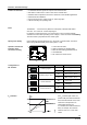
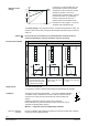
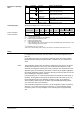
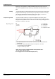
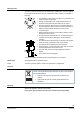

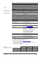
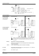
Table Of Contents

5/20
Siemens Modulating refrigerant valves with magnetic actuator, PS45 CE2N4714en
Smart Infrastructure 2021-08-02
LED
Indication
Function
Remarks, troubleshooting
Green
Lit
Control mode
Automatic operation; everything o.k.
Flashing
Calibration in
progress
Wait until calibration is finished
(green or red LED will be lit)
Red
Lit
Calibration error
Internal error
Recalibrate (operate button in opening 1x)
Replace electronics module
Flashing
Mains fault
Check mains network (outside the frequency or
voltage range)
Both
Dark
No power supply
Electronics faulty
Check mains network, check wiring
Replace electronics module
Always give preference to a 4-wire connection!
S
NA
P
MED
S
TR
P
TR
I
F
Wire cross-section [mm
2
]
1.5
2.5
4.0
2)
Product number
[VA]
[W]
[VA]
[W]
[A]
max. cable length L [m]
MVL661..-..
32
12
≥50
≥40
1.6…4 A
65
110
160
MVL661..-..
32
12
≥
50
≥
40
1.6…4 A
20
35
50
S
NA
= Nominal apparent power
P
med
= Typical power consumption in the application
S
TR
= Minimum apparent transformer power
P
TR
= Minimum DC supply power
I
F
= Minimal Required slow fuse
L = Max. cable length; with 4-wire connections, the max. permissible length of the separate 1.5 mm
2
copper positioning signal wire is 200 m
1)
All information at AC 24 V or DC 24V
2)
With 4 mm
2
electrical wiring reduce wiring cross-section for connection inside valve to 2.5 mm
2
.
Sizing
For straightforward valve sizing, refer to the tables for the relevant application (from
page 12).
For accurate valve sizing, we recommend to make use of the valve sizing software "
Refrigeration Valve Selection Program RVASP", available from your local Siemens
office.
The refrigeration capacity Q
0
is calculated by multiplying the mass flow by the specific
enthalpy differential found in the h, log p-chart for the relevant refrigerant. To help
determine the refrigeration capacity more easily, a selection chart is provided for each
application (page 12 and following). With direct or indirect hot-gas bypass applications,
the enthalpy differential of Q
c
(the condenser capacity) must also be taken into account
when calculating the refrigeration capacity.
If the evaporating and / or condensing temperatures are between the values shown in
the tables, the refrigeration capacity can be determined with reasonable accuracy by
linear interpolation (refer to the application examples on page 12 and following).
At the operating conditions given in the tables, the permissible differential pressure
∆p
max
across the valve is not considered.
If the evaporating temperature is raised by 1 K, the refrigeration capacity increases by
about 3%. If, by contrast, subcooling is increased by 1 K, the refrigeration capacity
increases by about 1 to 2% (this applies only to subcooling down to approximately
8 K).
Indication of operating
state
Connection type
1)
4-wire connection
3-wire connection
Notes