
Data Sheet for Product
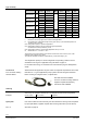
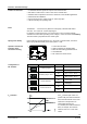
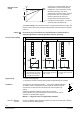
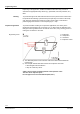

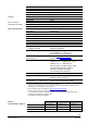
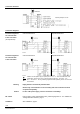
Table Of Contents

3/20
Siemens Modulating refrigerant valves with magnetic actuator, PS45 CE2N4714en
Smart Infrastructure 2021-08-02
Function / mechanical design
• 4 selectable standard signals for setpoint and measured value
• DIP switch to reduce the k
vs
value to 63% of the nominal value
• Potentiometer for adjustment of minimum stroke for suction throttle applications
• Automatic stroke calibration
• Forced control input for “Valve closed” or “Valve fully open”
• LED for indicating the operating state
The MVL661..-.. can be driven by Siemens or third-party controllers that deliver
a DC 0/2...10 V or DC 0/4...20 mA output signal.
For optimum control performance, we recommend a 4-wire connection between
controller and valve. When operating on DC voltage, a 4-wire connection is mandatory!
The valve stroke is proportional to the control signal.
If the positioning signal is interrupted, or in the event of a power failure, the valve’s
return spring will automatically close control path A → AB.
4716Z 15
2
on
1
2 3
4
G0
G Y U
M ZC
1
3
4 5
1 Connection terminals
2 LED for indication of operating state
3 Minimal stroke setting potentiometer Rv
4 Autocalibration
5 DIL switches for mode control
Switch
Function
ON / OFF
Description
1
ON
Positioning signal Y
ON Current [mA]
OFF Voltage [V]
1)
2
ON
Positioning range Y and U
ON DC 2…10 V, 4…20 mA
OFF DC 0…10 V, 0…20 mA
1)
3
ON
Position feedback U
ON Current [mA]
OFF Voltage [V]
1)
4
ON
Nominal flow rate k
vs
ON
63%
OFF
100%
1)
1)
Factory setting
For k
vs
reduction (DIL switch 4 in
position ON), the stroke is limited to
63% mechanical stroke. 63% of full
stroke then corresponds to an
input/output signal of 10 V.
If, in addition, the stroke is limited to
80%, for example, the minimum
stroke is 0.63 x 0.8 = 0.50 of full
stroke.
Features and benefits
Drive
Spring return facility
Operator controls and
indicators in the
electronics housing
Configuration of
DIL switches
k
vs
-reduction