
User Guide
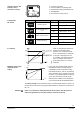
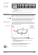

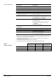

Connection diagrams
Common Transformer Separate Transformer
Terminal assi
gnment
for controller with
4-wire connection
(to be preferred!)
Common Transformer Separate Transformer
U
Indication of valve position (only if required). DC 0...10 V → 0...100 % volumetric flow V100
Twisted pairs. If the lines for AC 24 V power supply and the DC 0...10 V (DC 2...10 V,
DC 0... 20 mA, DC 4... 20 mA) positioning signal are routed separately, the AC 24 V line need
not be twisted.
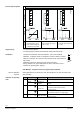
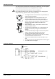
Terminal assi
gnment
for controller with
3-wire connection
Piping must be connected to potential earth!
War
ning
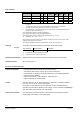
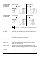
DIL switch Factory setting: Valve chara
cteristics equal-percentage, positioning signal DC 0...10 V.
Details see "Configuration DIL switches", page 3.
Calibration See "Calibration", page 4.
S
pecial conditions
See also ATEX valve supplementary sheet delivered with.
Cabling and wiring Cabling and wiring of CDV..MVL661.. must meet the requirement under EN 60079-15
Section 6.2.6. and for which an separate certificate exists (separate certified "EEx e"
cabling can be used).
Cable openings
Unused cable openings with knock outs must be closed accordingly. Separately
certified "EEx e" sealing plugs are used.
Degree of protection
Degree of protection (solid foreign object, dust and water protection) per IEC/EN
60529, at a minimum IP 54 for installation and in operation, is only achieved with proper
cabling and wiring as well as sealing plugs as required.
Protection against
UV radiation
The refrigerant valve CDV..MVL661.. must be installed in a manner providing sufficient
protection against sunlight and other sources of UV radiation.
7/12
Building Technologies Refrigerant Valves PS45 CE2Q4714en
HVAC Products 29.02.2012