
User Guide


4/12
Siemens Refrigerant Valves PS45 CE2Q4714en
Building Technologies 29.02.2012
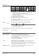
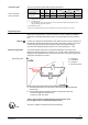
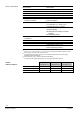
ZC – Function
no function fully open closed
Connections Transfer
GG
G
Function
• ZC not connected
• Valve will follow Y-signal
• Minimal stroke setting with
potentiometer Rv possible
• ZC connected with G
• Valve will fully open control
path A AB
• ZC connected with G0
• Valve will close control path
A AB
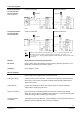
1. Forced control input ZC
2. Positioning signal Y and/or minimal stroke setting potentiometer Rv
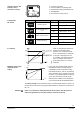
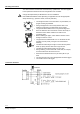
The printed circuit board of the CDV..MVL661.. has a slot to facilitate
calibration. To calibrate, insert a screwdriver in the slot so that the contacts
inside are connected. As a result, the valve will first be fully closed and then
fully opened.
Calibration matches the electronics to the valve mechanism.
During calibration, the green LED flashes for about 10 seconds; refer to "
Indication of operating state " (page 4).
01124
CDV..MVL661.. refrigerant valves are supplied fully calibrated.
After replacement of the electronics, when the red LED is lit, or when the valve (valve
seat) is leaking.
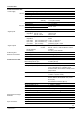
LED State Function Comment, action
Green Steady on
Operation
Automatic mode; everything ok
Flashing
Calibration in
progress
Wait until calibration is terminated (LED stops
flashing)
Red Steady on
Calibration error
Internal error
Start stroke calibration again
(short-circuit contacts via slot in PCB)
Replace electronics
Flashing
Mains fault
Check mains power supply
(e.g. outside the frequency or voltage range)
Both Off
No power supply
Faulty electronics
Check mains power supply, check wiring
Replace electronics
Forced control input ZC
Signal priority
Calibration
When is calibration
required?
Indication of operating
state