
User Guide


4716Z15
2
on
1234
G0 G Y UMZC
1
3
45
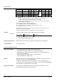
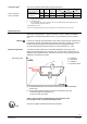
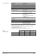
1 Connection terminals
2 LED for indication of operating state
3 Minimal stroke setting potentiometer Rv
4 Autocalibration
5 DIL switches for mode control
Oper
ator controls and
indicators in the
electronics housing
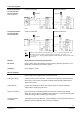
DIL switch Function ON / OFF Description
ON Current [mA]
1
ON
positioning signal Y
OFF Voltage [V]
1)
ON DC 2…10 V, 4…20 mA
2
ON
Positioning signal range Y
and U
OFF DC 0…10 V, 0…20 mA
1)
ON Current [mA]
3
ON
4714Z04
Position feedback signal U
OFF Voltage [V]
1)
ON 63 %
4
ON
Nominal flow rate k
vs
OFF 100 %
1)
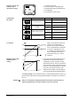
Configur
ation
DIL switch
1)
Factory setting
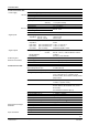
When k
vs
reduction (DIL switch 4 in
position on) the stroke will be
limited to 63 % mechanical stroke.
63 % of full stroke then corresponds
to an input / output signal of 10 V.
If, in addition, the stroke is limited to
80 %, for example, the minimum
stroke will be 0.63 x 0.8 = 0.50 of
full stroke.
k
vs
reduction
80 %
100 %
4716D01en
0 %
0 % 100 %
Y-inp ut
Stroke
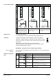
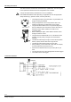
In the case of the suction throttle valve, it is
essential that a minimum stroke limit be
maintained to ensure compressor cooling
and efficient oil return. This can be achieved
with a reinjection valve, a bypass line across
the valve, or a guaranteed minimum opening
of the valve. The minimum stroke can be
defined via the controller and control signal Y,
or it can be set directly with potentiometer Rv.
Minimum opening with
min
imum stroke
setting
The factory
setting is zero (mechanical stop in counterclockwise direction, CCW). The
minimum stroke can be set by turning the potentiometer Rv clockwise to a maximum of
80 % k
vs
.
Attention
Under no circ
umstances must potentiometer Rv be used to limit the stroke on
expansion applications. It must be possible to close the valve fully.
3/12
Building Technologies Refrigerant Valves PS45 CE2Q4714en
HVAC Products 29.02.2012