
User Guide
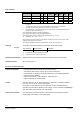

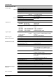

Type summary
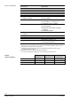
Type reference Base valve
3)
DN k
vs
k
vs
reduced
1)
Δp
max
Q
0
E Q
0
H Q
0
D
[m
3
/h] [m
3
/h] [MPa] [kW] [kW] [kW]
CDV..MVL.. MVL661.15-0.4 15 0.40 0.25 47 9.2 1.7
CDV..MVL.. MVL661.15-1.0 15 1.0 0.63 117 23 4,2
CDV..MVL.. MVL661.20-2.5 20 2.5 1.6 293 57 10
CDV..MVL.. MVL661.25-6.3 25 6.3 4.0
2,5
737 144 26
1)
k
vs
and Q
0
refrigeration capacity can be reduced to 63 % of nominal k
vs
, refer to «kvs
reduction»
on page 3
2)
The data sheet references for ease of understanding and reading to CDV..MVL661..
3)
For ease of use and understanding CDV..MVL661.. is used as term.
k
vs
Nominal flow rate of refrigerant through the fully open valve (H
100
) at a differential pressure of
100 kPa (1 bar) to VDI / VDE 2173
Q
0
E Refrigeration capacity in expansion applications
Q
0
H Refrigeration capacity in hot-gas bypass applications
Q
0
D Refrigeration capacity in suction throttle applications and Δp = 0.5 bar
Q
0
With R407C at t
0
= 0 °C, t
c
= 40 °C
The pressure drop across evaporator and condenser is assumed to be 0.3 bar each, and 1.6 bar
upstream of the evaporator (e.g. spider).
The capacities specified are based on superheating by 6 K and sub-cooling by 2 K.
Or
dering The product may only be ord
ered as customized device variant (CDV).
Ex
ample
Type reference Stock number Description
CDVxxMVLyy CDV..MVL.. Refrigerant valve
xx 5-digit number created especially for a CDV or
yy Sequence number created for CDVV order
Replacement electronics
Replacement electronics may be ordered as customized device variant (CDV).
Re
vision numbers
See overvie
w, page 11.
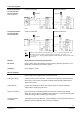
Functio
n / mechanical design
• Four selectable standard signals for set and actual value Features and benefits
• DIL switch to reduce the k
vs
value to 63 % of the nominal value
• Potentiometer for adjustment of minimum stroke for suction throttle applications
• Automatic stroke calibration
• Forced control input for “Valve closed” or “Valve fully open”
• LED for indicating the operating state
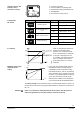
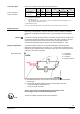
Contr
ol
The CDV..M
VL661.. can be driven by Siemens or third-party controllers that deliver
a DC 0/2...10 V or DC 0/4...20 mA output signal.
For optimum control performance, we recommend a 4-wire connection between
controller and valve. When operating on DC voltage, a 4-wire connection is mandatory!
The valve stroke is proportional to the control signal.
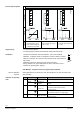
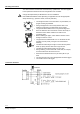
Sp
ring return function
The return spring causes the
actuator to close the valves control path A AB on
power failure or interruption of the control signal.
2/12
Siemens Refrigerant Valves PS45 CE2Q4714en
Building Technologies 29.02.2012