
Data Sheet for Product


MVL661… Modulating Refrigerant Valves Technical Instructions
Valves with Magnetic Actuator Document Number 155-400
May 11, 2016
Page 7
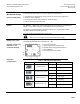
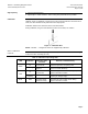
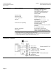
Expansion application
To prevent formation of flash gas on expansion applications, the velocity of the refrigerant
in the fluid pipe may not exceed 3.5 ft/s (1 m/s). To assure this, the diameter of the fluid
pipe must be greater than the nominal size of the valve, using reducing pieces for making
the connections to the valve.
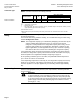
1 = Evaporator
2 = Compressor
3 = Condenser
4 = Expansion
valves
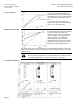
a) The differential pressure over reduction must be less than half the differential pressure
Δp
FL
.
b) The inlet path between diameter reduction and expansion valve inlet
Must straight for at least 2 feet (600 mm)
May not contain any valves
WARNING:
A filter/dryer must be mounted upstream of the expansion valve.
The valve is not explosion-proof.
It is not approved for use with ammonia (NH3, R717).
Installation Notes
The valve should be mounted and commissioned by a qualified installer. The same
applies to the replacement electronics and the configuration of the controller.
The refrigerant valves can be mounted in any orientation
above horizontal, but upright mounting is preferable.
Arrange the pipework so that the valve is not located at a
low point in the plant where oil can collect.
The pipes should be fitted so that the alignment does not
distort the valve connections. Fix the valve body so that
that it cannot vibrate. Vibration can lead to burst connection
pipes.
Before soldering the pipes, ensure that the direction of flow
through the valve is correct.
The pipes must be soldered with care. To avoid dirt and the
formation of scale (oxide), inert gas is recommended for
soldering.