
User Manual

7 / 16
Siemens Control device PN40, safety function to DIN EN 14597 CE1N4388en
Smart Infrastructure 2020-01-09
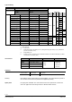
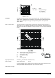
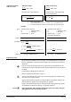
Flow k
v
/ k
vs
0,8
0,6
0,4
0,2
0
1
0 0,2 0,4 0,6 0,8 1
0…30 % → linear
30…100 % → equal percentage
n
gl
= 3 as per
VDI / VDE 2173
Stroke H / H
100
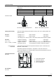
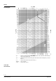
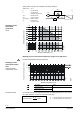
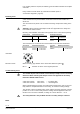
Cavitation accelerates wear on the valve plug and seat, and also results in unde-
sirable noise. Cavitation can be avoided by not exceeding the differential pressure
shown in the flow diagram on page 5 and by adhering to the static pressures
shown below.
To avoid cavitation in chilled water circuits ensure sufficient counter pressure at
valve outlet, e.g. by a throttling valve after the heat exchanger. Select the pressure
drop across the valve at maximum according to the 80 °C curve in the flow diagram
below.
0 100 200 300 400 500 600 700 800 900 1000 1100 12001300
25
20
15
10
5
0
2500
2000
1500
1000
500
0
1
4
0
°
C
1
8
0
°
C
1
6
0
°
C
1
2
0
°
C
1
0
0
°
C
8
0
°
C
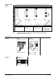
p
max
= Differential pressure with valve almost closed, at
which cavitation can largely be avoided
p
1
= Static pressure at inlet
p
3
= Static pressure at outlet
M = Pump
= Water temperature
p
3
p
1
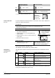
Pressure p
1
at valve inlet: 500 kPa (5 bar)
Water temperature: 120 °C
From the diagram above, it will be seen that with the valve almost closed, the max-
imum permissible differential pressure p
max
is 200 kPa (2 bar).
Cavitation
Note on chilled water
High temperature hot
water example:
Chilled water example: