
User Manual

15 / 16
Siemens Control device PN40, safety function to DIN EN 14597 CE1N4388en
Smart Infrastructure 2020-01-09
c1
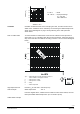
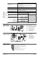
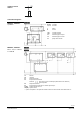
Connection diagrams
F1 temperature limiter
N1, N2 controller
Y1, Y2 actuators
L Phase
N neutral
(Y1) controller contacts
(Y2) controller contacts
Y1 Positioning signal «open»
Y2 Positioning signal «close»
21 spring-return function
Y1 actuator
N1 controller
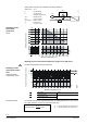
F1 temperature limiter
F2 frost protection thermostat
terminals: 1 – 2 frost hazard / sensor is interrupted (thermostat closes with frost)
1 – 3 normal operation
F3 temperature detector
F4 frost protection monitor with 0…1000 Ω signal output *
G (SP) System potential AC 24 V
G0 (SN) System neutral
* QAF21.. and QAF61.. frost protection monitor cannot be connected with control devices MK..6...
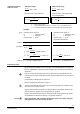
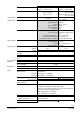
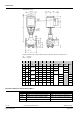
Auxiliary switch
ASC1.6
MKB632.., MKC632..
3-position
MKB662.., MKC662..
DC 0…10 V, 4…20 mA,
0…1000 Ω