s 4 388 ACVATIX™ Control device PN40, safety function to DIN EN 14597 MK..6.. Preassembled valve-actuator combinations • MK..632.. Operating voltage AC 230 V, 3-position control signal • MK..662.. Operating voltage AC 24 V, control signal DC 0...10 V, 4...20 mA or 0...1000 Ω • MK..662..
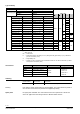
Type summary Control device MKB632.., MKC632.. MKB662.., MKC662.. Operating voltage Electrohydraulic actuator 2800 N, 120 s Positioning signal AC 230 V AC 24 V 2-port valve DC 0…10 V, DC 4…20 mA, 0…1000 Ω 3-position Product number MKB632.15-0.19 2) Stock number Product number S55329-M180-A110 MKB662.15-0.19 2) Stock number S55329-M180-A111 MKB632.15-0.3 2) S55329-M181-A110 MKB662.15-0.3 2) S55329-M181-A111 MKB632.15-0.45 2) S55329-M182-A110 MKB662.15-0.45 2) S55329-M182-A111 MKB632.15-0.
Technical design The functional principle and technical details are described in valve and actuator data sheets: Product Electrohydraulic actuators Electrohydraulic actuators 2-port valves Type SKB.. SKC.. VVF61.. Data sheet N4564 N4566 N4382 Direction of flow DN 40…150: closes on pressure DN 15/ 25: closes against pressure Spring return facility The return spring causes the actuator to move to the «0 %» stroke position and closes the valve. MK..632..
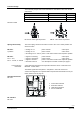
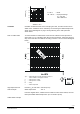
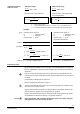
Positioning signal Y Position feedback U 4567Z05 12 DC 0…10 V 12 log = equal-percentage *) Factory setting: All switches OFF V100 Relationship between control signal Y and volumetric flow Stroke calibration MK..662..
Override control input Z MK..662..
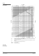
Sizing Flow diagram pmax = pv100 = = V 100 100 kPa = 1 m3/h = Maximum permissible differential pressure across the valve, valid for the entire actuating range of the motorized valve Differential pressure across the fully open valve and the valve’s control path by a volume flow V100 Volume flow through the fully open valve (H100) 1 bar 10 mWC 0.
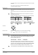
Flow kv / kvs 1 0,8 0…30 % → linear 30…100 % → equal percentage ngl = 3 as per VDI / VDE 2173 0,6 0,4 0,2 0 0 0,2 0,4 0,6 0,8 1 Stroke H / H100 Cavitation Cavitation accelerates wear on the valve plug and seat, and also results in undesirable noise. Cavitation can be avoided by not exceeding the differential pressure shown in the flow diagram on page 5 and by adhering to the static pressures shown below.
Spring water cooling as an example of avoiding cavitation: Chilled water = 12 °C = 500 kPa (5 bar) p4 = 100 kPa (1 bar) (atmospheric pressure) pmax = 300 kPa (3 bar) p3-3’ = 20 kPa (0.2 bar) M p1 p4 4382Z07 pmax p1 p3 p3' pD (throttle) = 80 kPa (0.
Calculation of the kvs value for steam Subcritical range Supercritical range p1 − p3 100% 42% p1 p1 − p3 100% 42% P1 Pressure ratio < 42% subcritical Pressure ratio 42% supercritical (not recommended) k vs = 4.4 m p3 (p1 − p3 ) k vs = 8.8 k m k p1 = steam quantity in kg/h m k = factor for superheating of steam = 1 + 0.
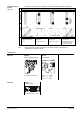
If an auxiliary switch is required, its switching point should be indicated on the plant schematic. Every actuator must be driven by a dedicated controller (refer to «Connection diagrams», page 15). Mounting notes Valve and actuator are preassembled and must be mounted and installed as a whole unit. The control device is preset to 50 % stroke for flushing and pressure testing of the plant.
Cylinder with valve stem connector fully extended → stroke = 100 % 0 1 0 1 Automatic operation 4564Z13 4564Z12 Cylinder with valve stem connector fully retracted → stroke = 0% The control device can only be operated in automatic mode. The crank (2) on the manual adjustment knob (1) is engaged and secured with antitamper screws. 1 2 When removing anti-tamper screws (3) TÜV approval for the safety function to DIN EN 14597 ceases.
Disposal The device contains electrical and electronic components and must not be disposed of together with domestic waste. This applies in particular to the PCB. Before disposal the valve must be dismantled and separated into its various constituent materials. Legislation may demand special handling of certain components, or it may be sensible from an ecological point of view. Current local legislation must be observed.
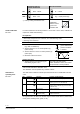
MKB632.. MKC632.. Max. Power consumption at 50 Hz MKB632..: 15 VA / 13 W MKC632..: 24 VA / 21 W External supply cable fuse min. 0.5 A, slow max. 6 A, slow Signal inputs Control signal Y Signal inputs Terminal Y 3-position Voltage Input impedance Current Input impedance Signal resolution Hysteresis Resistor Z not connected Override control Z Signal outputs Z connected directly to G Z connected directly to G0 Z connected to M via 0...
Environmental compatibility Pressure Equipment Directive Accessories with safety functions Fluid group 2 Flange connections Accessories ASC1.6 Auxiliary switch ASC9.3 double auxiliary switch ASZ7.3 Potentiometer MKB632.. MKC632.. MKB662.. MKC662.. ISO 14001 (Environment) ISO 9001 (Quality) SN 36350 (Environmentally compatible products) RL 2002/95/EG (RoHS) PED 97/23/EC As per article 3, section 1.
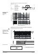
Auxiliary switch ASC1.6 c1 Connection diagrams MKB632.., MKC632.. 3-position F1 N1, N2 Y1, Y2 temperature limiter controller actuators L N Phase neutral (Y1) (Y2) Y1 Y2 controller contacts controller contacts Positioning signal «open» Positioning signal «close» 21 spring-return function MKB662.., MKC662..
Dimensions All dimensions in mm Minimum clearance from ceiling or wall for mounting, connection, operation, maintenance etc. ► = > 100 mm ►► = > 200 mm DN B D D2 Ø Ø 15 16 95 D4 K L1 L2 L3 kg H Ø Ø 46 65 130 65 90 471 16,3 67 85 160 80 107 486 18,9 84 110 200 100 102 99 125 230 115 107 118 145 290 145 138 537 39,5 132 160 310 155 150 545 45,5 235 22 (8x) 156 190 350 175 173 555 62.