
User Manual

6/12
Siemens 2-port seat valves PN25 with flanged connection CM1N4373en
Building Technologies 15.11.2010
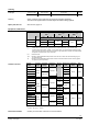
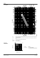
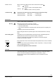
Cavitation accelerates wear on the valve plug and seat, and also results in undesirable
noise. Cavitation can be avoided by not exceeding the differential pressure shown in
the flow diagram on page 5 and by adhering to the static pressures shown below.
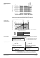
To avoid cavitation in chilled water circuits ensure sufficient counter pressure at valve
outlet, e.g. by a throttling valve after the heat exchanger. Select the pressure drop
across the valve at maximum according to the 80 °C curve in the flow diagram below.
0 100 200 300 400 500 600 700 800 900 10001100 1200 1300
25
20
15
10
5
0
2500
2000
1500
1000
500
0
P
1
[kPa]
P
1
[bar]
p
max
[kPa]
4382D05
1
4
0
°
C
1
8
0
°
C
1
6
0
°
C
1
2
0
°
C
1
0
0
°
C
8
0
°
C
p
max
= Differential pressure with valve almost closed, at which
cavitation can largely be avoided
p
1
= Static pressure at inlet
p
3
= Static pressure at outlet
M = Pump
= Water temperature
p
3
p
1
4
3
8
2
Z
0
6
p
max
M
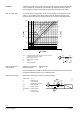
Pressure p
1
at valve inlet: 500 kPa (5 bar)
Water temperature: 120 °C
From the diagram above, it will be seen that with the valve almost closed, the maximum
permissible differential pressure p
max
is 200 kPa (2 bar).
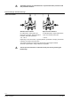
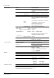
Spring water cooling as an example of avoiding cavitation:
Chilled water = 12 °C
p
1
= 500 kPa (5 bar)
p
4
= 100 kPa (1 bar)
(atmospheric pressure)
p
max
= 300 kPa (3 bar)
p
3-3’
= 20 kPa (0,2 bar)
p
D
(throttle) = 80 kPa (0,8 bar)
p
3
’ = pressure after
consumer in kPa
p
3
p
1
4
3
8
2
Z
0
7
p
max
M
p
3
'
p
D
p
4
Cavitation
Note on chilled water
High temperature hot
water example:
Chilled water example: