
User Manual

8 / 14
Siemens Control device PN25, safety function to DIN EN 14597 CE1N4389en
Building Technologies 10.01.2011
Engineering notes
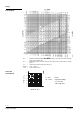
The use of these valves for steam is subject to specific parameters: Observe dia-
gram for steam on page 7 and "Technical data" on page 10!
To ensure the reliability of the valve, we recommend the fitting of a
strainer at the
valve inlet even in closed circuits.
Conduct the electrical connections in accordance with local regulations on electri-
cal installations as well as the internal or connection diagrams.
Safety regulations and restrictions designed to ensure the safety of people
and property must be observed at all times!
Observe admissible temperatures, refer to «Use» on page 1 and «Technical data»
on pag
e 10.
If an auxiliary switch is req
uired, its switching point should be indicated on the plant
schematic.
Every actuator must be driven by a dedicated controller (refer to
«Connection diagrams», page 13).
Mounting no
tes
Valve and actuator are preassembled and must be mounted and installed as a whole
unit.
The control device is preset to 50 % stroke for flushing and pressure testing of the
plant.
Attention: When removing anti-tamper screws TÜV approval for the safety function to
DIN EN 14597 ceases!
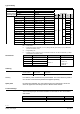
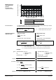
Mounting and installation instructions are by packed in the control device packing.
Control device Installation instruction Mounting instructions
MKB..32.. - - M3240 4 319 0324 0
- - M4300 74 319 0509 0
MKB562..G - 4 319 0326 0 M3240 4 319 0324 0
- - M4300 74 319 0509 0
The instructions for accessories are enclosed with the accessories themselves.
Accessories Installation instructions Accesso-
ries
Mounting instructions
ASC1.6 G4563.3 4 319 5544 0 ASZ7.3.. - 74 319 0247 0
ASC9.3 G4561.3 4 319 5545 0
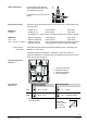
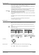
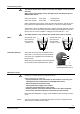
90°
90°
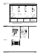
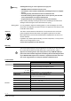
When mounting, pay attention to the valve's flow direction symbol →.
MK..5..G → Direction of action: closes against pressure
Caution
Orientation
Direction of flow