
User Manual

4 / 14
Siemens Control device PN25, safety function to DIN EN 14597 CE1N4389en
Building Technologies 10.01.2011
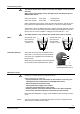
In order to determine the stroke positions 0 % and 100 % in the valve, calibration is
required on initial commissioning:
Prerequisites
• Red safety clamp is removed, see “Commissioning notes”, page 9
• AC 24 V power supply
• Housing cover removed
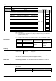
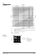
Calibration
01124
green LED flashes;
position feedback
U inactive
1. Short-circuit contacts in calibration slot
(e.g. with a screwdriver)
2. Actuator moves to «0 %» stroke position (1)
(valve closed)
3. Actuator moves to «100 %» stroke position (2)
(valve open)
4. Measured values are stored
0%
t
100%
Stroke
1
2
3
4567Z09
Normal operation
5. Actuator moves to the position (3) as
indicated by signals Y or Z
green LED is lit permanently;
position feedback U active, the values
correspond to the actual positions
A lit red LED indicates a calibration error.
The calibration can be repeated any number of times.
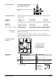
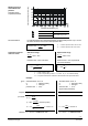
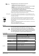
The LED status indication indicates operational status and is visible with removed
cover.
LED Indication Function Remarks, troubleshooting
Green Lit Normal operation Automatic operation; everything o.k.
Flashing
Calibration in progress Wait until calibration is finished (LED stops
flashing, green or red LED will be lit)
Faulty stroke calibration Check mounting
Restart stroke calibration (by short-circuiting
calibration slot)
Red Lit
Internal error Replace electronics
Flashing
Inner valve jammed Check valve
Both Dark
No power supply
Electronics faulty
Check mains network, check wiring
Replace electronics
As a general rule, the LED can assume only the states shown above (continuously
red or green, flashing red or green, or off).
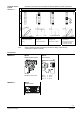
Stroke calibration
MKB562..G
Indication of
operating state
MKB562..G