
User Manual

3 / 14
Siemens Control device PN25, safety function to DIN EN 14597 CE1N4389en
Building Technologies 10.01.2011
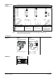
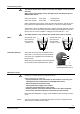
For applications with saturated
steam, super-heated steam up to
max. 600 kPa (6 bar) abs
Pay attention to the valve's flow di-
rection.
The return spring causes the actuator to move to the «0 %» stroke position and
closes the valve.
• Voltage on Y1 piston extends valve opens
• Voltage on Y2 piston retracts valve closes
• No voltage on Y1 and Y2 piston / valve stem remain in the respective position
• Signal Y increasing: piston extends valve opens
• Signal Y decreasing: piston retracts valve closes
• Signal Y constant: piston / valve stem remain in the respective position
• Override control Z see description of override control input, page 5
A frost prote
ction thermostat or temperature detector can be connected to the
MKB562..G control device.
The added signals from the QAF21.. and QAF61.. cannot be connected.
«Connection diagrams» for operation with frost protection thermostat or frost pro-
tection monitor refer to page 13.
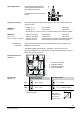
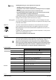
4567Z03
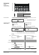
Calib.
Status
ok
calib.
error
valve
jam
green
red
Status
Calib.
0...10V
4...20mA
Z
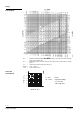
1 Connection terminals
2 Mode DIL switches
3 LED status indication
4 Slot for calibration
Positioning signal Y
Position feedback U
Flow characteristic
ON
ON
1 2
4567Z05
DC 4…20 mA
ON
21
4567Z07
lin = linear
OFF *)
ON
1 2
4567Z06
DC 0…10 V
ON
21
4567Z08
log = equal-percentage
*) Factory setting:
All switches OFF
Relationship
between control
signal Y and
volumetric flow
0
4
l
i
n
l
o
g
V
100
V
0
10 V
20 mA
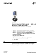
Steam applications
Spring return facility
MKB532..G
3-position
MKB562..G
DC 0...10 V,
DC 4… 20 mA, 0...1000 Ω
Frost protection
thermostat
Standard electronics
MKB562..G
DIL switches
MKB562..G