
User Manual


12 / 14
Siemens Control device PN25, safety function to DIN EN 14597 CE1N4389en
Building Technologies 10.01.2011
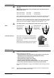
MKB532..G MKB562..G
Conform with C-tick N474
Environmental compatibility ISO 14001 (Environment)
ISO 9001 (Quality)
SN 36350 (Environmentally compatible products)
RL 2002/95/EG (RoHS)
Pressure Equipment Directive
PED 97/23/EC
Accessories with safety func-
tions
As per article 3, section 1.4
Fluid group 2
Category IV, with EC design examination module B,
test authority number 0036
Flange connections to ISO 7005
Accessories
ASC1.6
Auxiliary switch
Switching capacity AC 24 V,
10 mA...4 A ohm.,
2 A ind.
ASC9.3
double auxil-
iary switch
Switching capacity per auxiliary
switch
AC 250 V, 6 A ohm., 2.5 A ind.
ASZ7.3
Potentiometer
Change in overall resistance of
potentiometer at nominal stroke
ASZ7.3 0…1000 Ω
ASZ7.31 0…135 Ω
ASZ7.32 0…200 Ω
min. current in sliding contact 0.05 mA
expected lifetime 250'000 full lifts
max. current in sliding contact 2.5 mA
expected lifetime 100'000 Full lifts
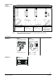
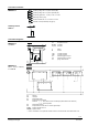
Internal diagrams
MKB532..G
AC 230 V, 3-position
c
0 %
0 %
Cm1
Cm1 end switch
n solenoid valve for spring-return
c1, c2 ASC9.3 double auxiliary switch
a, b, c ASZ7.. potentiometer
Y1 Positioning signal «open»
Y2 Positioning signal «close»
21 spring-return function
N neutral conductor
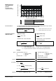
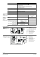
MKB562..G
AC 24 V, DC 0…10 V,
4…20 mA, 0…1000
U
Y
M
G0
G
MMI
Eingang
Zwangsteuerung
(Signalpriorität)
Eingang
Valve Seat
Detection
Val ve Jam
Detection
DC 0 ...10 V
oder
4 ... 20 mA
DC 0 ...10 V
oder
4 ... 20 mA
voll offen
0 ...100 %
0 ...100 %
Hub
Ventil
A
usgang
U position indication
Z override control
Y positioning signal
M measuring neutral
G0 operating voltage AC 24 V:
system neutral (SN)
G operating voltage AC 24 V:
system potential (SP)