
User Manual


11 / 14
Siemens Control device PN25, safety function to DIN EN 14597 CE1N4389en
Building Technologies 10.01.2011
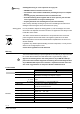
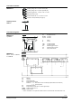
MKB532..G MKB562..G
Actuators
Power supply Operating voltage
Voltage tolerance
AC 230 V
± 15 %
AC 24 V
–20 % / +30 %
SELV / PELV
Frequency 50 or 60 Hz
Max. Power consumption at
50 Hz
15 VA / 13 W 17 VA / 12 W
External supply cable fuse min. 0.5 A, slow
max. 6 A, slow
min. 1 A, slow
max. 10 A, slow
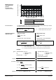
Signal inputs Control signal Y
3-position
DC 0...10 V, DC 4...20 mA
or 0...1000
Terminal Y Voltage DC 0…10 V
Input impedance 100 k
Current DC 4…20 mA
Input impedance 240
Signal resolution < 1%
Hysteresis 1 %
Override control Z Resistor 1000
Z not connected No function, priority ter-
minal Y
Z connected directly to G max. stroke 100 %
Z connected directly to G0 min. stroke 0 %
Z connected to M via 0...1000 Ω stroke proportional to R
Position feedback U voltage DC 0...9.8 V ±2 % Signal outputs
load impedance > 10 k
current DC 4...19.6 mA ±2 %
load impedance < 500
Operational
data
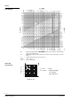
Positioning time at 50 Hz
opening
120 s
closing 120 s 10 s
Spring-return time
(closing)
5…25 s
Nominal stroke 20 mm
Max. permissible medium tem-
perature
+1…180 °C
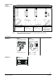
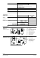
El. Connections Cable entry 4 x M20 (∅ 20.5 mm)
Materials Actuator housing, bracket Die-cast aluminum
Housing box and
manual adjuster
Plastic
Dimensions Dimensions Refer to "Dimensions", page 14
Weights Refer to "Dimensions", page 14
Norms CE-conformity
EMC-directive
2004/108/EC
Immunity
EN 61000-6-2 Industrial
Emission EN 61000-6-3 Residential
Low voltage directive 2006/95/EC
Electrical safety EN 60730-1
Product standards for auto-
matic electric controls
EN 60730-2-14
Control device with safety
function
DIN EN 14597
Temperature control devices and temperature
limiters for heat generating systems; Actuator devices with safety
functions in heat generating systems
Registration no.: 1F137/10
Protection standard EN 60730 I III
Housing protection standard
Upright to horizontal
IP54 to EN 60529