
Data Sheet for Product


M3PFY..Series Modulating Control Valve Technical Instructions
ANSI 125 (PN 16) with Magnetic Actuator Document No. CA1N4454E-P25
January 17, 2003
Siemens Building Technologies, Inc. Page 5
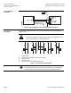
Wiring
Connection Terminals
WARNING:
If the controller and valves receive their power supplies from separate
sources, the valve transformer must not be grounded on the secondary
side.
1
2
3
4
6
TE
5
24 VAC supply
Common 0 - 10 VDC
Input 0 - 10 VDC
Output 0 - 10 VDC
Input 4 - 20 mA
SVAL0084R1
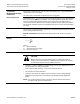
Figure 3. Terminal Layout.
1
2
3
5
4
Output 0 - 10 VDC
Input4-20mA
Input0-10VDC
T
24 VAC
~
G
V
Position feedback electronics
with base/span adjustment
Position
transducer
E
Q
M
–
+
NS
LS
T
V
U
+
–
R
SVAL0083R1
Figure 4. Block Diagram of Signal Converter.
.H\
E Phase cut converter
G Bridge rectifier
M Magnetic valve
Q Phase cut output
R Input resistor 50K ohms
T Voltage/current converter
(load on 350 ohms to NS)
U Position/voltage converter
V Differential amplifier
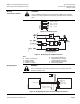
Wiring Diagrams
WARNING:
The T2 transformer must not be grounded on the secondary side and
should be suitably fused.
1
2
3
4
6
U
5
1
)
24 VAC Supply
Common
Output 0 - 10 VDC
~
T E
Input 0 - 10 VDC
Valve position indication
0 - 10 VDC = 0 - 100 %
Output 0 - 10 VDC
24 VAC
T2
SVAL0086R1
Figure 5. Wiring Diagram with 0 to 10 Vdc Output Controllers.