
Data Sheet for Product


Technical Instructions M3PFY..Series Modulating Control Valve
Document No. CA1N4454E-P25 ANSI 125 (PN 16) with Magnetic Actuator
January 17, 2003
Page 4 Siemens Building Technologies, Inc.
Installation,
Continued
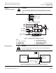
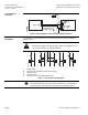
Straight-through
Application
The blank flange kit consists of a seal, screws, spring washers and nuts.
• For 3-inch to 4-inch Blank Flange Kit (Z155/80 ... Z155/100)
SVAL0022R1
Z155/80
Z155/100
2
Figure 2. Straight-through Application.
Specifications
Electrical interface Class 2
Control signal 0 to 10 Vdc or 4 to 20 mA
Supply voltage 24 Vac, 50/60 Hz
– Maximum voltage tolerance +15/–10%
Nominal power See Table 1
Position feedback (output signal): 0 to 10 Vdc = 0 to 100% stroke
Maximum load 1.5 mA
Accuracy ±3% of full scale
Nominal pressure ANSI 125 (PN16)
Operating pressure p
e
max 14 psi (10 bar)
Pressure differential
∆p
v
max See Table 1
Leakage at
∆p
v
= 14.5 psi (1bar) 1 3 Maximum 0.03% C
V
2
3 Depends on application data
(approximately 2% C
V
)
Water temperature 35 to 248°F (2 to 120°C)
Valve characteristic (stroke, kv) Linear, optimized in low-opening range
Resolution ∆H / H100 >1: 1000 (H = stroke)
Type of operation Modulating
Manual adjustment 0% to maximum 90% depending on
line size
Position when de-energized 1
3 closed
Orientation Upright to horizontal
Positioning time <1 second
Materials (valve body):
Housing Cast iron
Inner valve Steel
Seat Brass
Valve spindle seal EPDM (O-ring)
Connection terminals Screw terminals for maximum 12 AWG
wire
Ambient temperature 35°F to 122°F (2°C to 50°C)
Weight (including packaging) See Dimensions
Conformity Meets CE requirements