
Data Sheet for Product


Technical Instructions M3PFY..Series Modulating Control Valve
Document No. CA1N4454E-P25 ANSI 125 (PN 16) with Magnetic Actuator
January 17, 2003
Page 2 Siemens Building Technologies, Inc.
Warning/Caution Notations
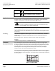
WARNING:
Personal injury or loss of life may occur if you
do not perform a procedure as specified.
CAUTION:
Equipment damage or loss of data may occur if
you do not follow a procedure as specified.
Application
The M3P...FY valves are mixing or straight-through port valves with a ready-mounted
magnetic actuator. The actuator has electronics for positioning control and position
feedback. If the power is off, the valve control path 1
3 is closed.
CAUTION:
The valve is suitable for straight-through or three-way applications and
may be installed only in a mixing arrangement.
The short positioning time, high resolution and high rangeability make these valves
ideal for proportional control of hot and chilled water systems.
The low-friction, heavy-duty and maintenance-free construction makes regular service
unnecessary.
Ordering
The valves are supplied with the magnetic actuator and terminal housing. The blank
flanges required for straight-through applications must be ordered separately (see
Accessories).
When placing an order, specify the quantity, product number and description.
Example:
1 M3P80FY flanged valve and 1 Z155/80 blank flange
Technical/
Mechanical Design
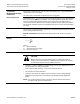
The control signal is converted in the terminal housing into a phase cut signal that
generates a magnetic field in the coil. This causes the only moving part, the armature,
to change its position in accordance with the interacting forces (magnetic field, counter-
spring, hydraulics, etc.). The armature responds rapidly to any change in signal,
transferring the corresponding movement directly to the control disc, enabling fast
changes in load to be corrected quickly and accurately.
The valve position is measured continuously. Any disturbance in the system is rapidly
corrected by the internal positioning controller, which ensures that the control signal and
the valve stroke are exactly proportional, and also provides a feedback signal indicating
the valve position.
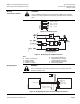
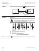
100
80
60
40
20
0
0
2
46
8
10
Sval0012R1
Figure 1. Position-signal.