
User Manual


4/10
Building Technologies Modulating Control Valve PN 16 with Magnetic Actuator CA2N4741en
HVAC Products 2018-02-14
To determine the volumetric flow
V
%
100
in case of anti-freeze proportions > 20 % use the
following formula:
Ζ ∴
hm
fT
Q
V /
.
3
1
100
100
1631 √Χ√
<
%
V
%
100
= Volumetric flow [m
3
/h]
Q
100
= Nominal system output [kW]
∆T = Temperature differential
between flow and return
[K]
f
1
= Correction factor
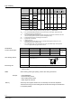
The correction factor f
1
can be taken from the following table or calculated with the
formula below.
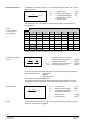
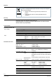
Temperature [°C]
N [%] -40 -20 0 20 40 60 80 100
100 0.60 0.62 0.63 0.65 0.67 0.68 0.69 0.71
80 0.71 0.73 0.74 0.75 0.77 0.78 0.79 0.80
60 0.79 0.80 0.81 0.82 0.84 0.85 0.86 0.86
52 0.82 0.83 0.84 0.85 0.86 0.87 0.88 0.88
44 0.87 0.88 0.88 0.89 0.90 0.90 0.90
34 0.92 0.92 0.92 0.92 0.92 0.93 0.93
20 0.97 0.97 0.97 0.96 0.96 0.95
The data and application notes of the anti-freeze manufacturer are binding.
1000
18
4
3
1
√
<
m
kg
kgK
kJ
c
f
θ
.
f
1
= Correction factor = 1 for water
c = Specific heat of anti-freeze [kJ/kgK]
θ = Density of anti-freeze [kg/m
3
]
4.18 = Specific heat of water at 20 °C [kJ/kgK]
1000 = Density of water at 20 °C [kg/m
3
]
For valve sizing with media other than water, note that the following media properties
differ from those of water. • specific heat
• density
• kinematic tenacity
All variables are temperature-dependent.
The design temperature equals the lowest media temperature prevailing in the valve.
Ζ ∴
hm
Tc
Q
V /
3
100
100
3600
θ
√Χ√
√
<
%
V
%
100
= Volumetric flow [m
3
/h]
Q
100
= Nominal system output [kW]
∆T = Temperature differential
between flow and return
[K]
c = Specific heat [kJ/kgK]
ρ = Specific density [kg/m
3
]
In HVAC plants, the kinematic viscosity τ [mm
2
/s] is always below 20 mm
2
/s so that its
impact on volumetric flow is negligible
Water with additives
Table
correction factor f
1
for Antifrogen N:
Calculation correction
factor f
1
:
General formula:
Note