
User Manual


3/10
Building Technologies Modulating Control Valve PN 16 with Magnetic Actuator CA2N4741en
HVAC Products 2018-02-14
Technical and mechanical design
For a detailed description of operation, refer to Data Sheet CA1N4028E.
The electronics module converts the positioning signal to a phase-cut power signal
which generates a magnetic field in the coil. This causes the armature to change its
position in accordance with the interacting forces (magnetic field, counterspring,
hydraulics, etc.). The armature responds rapidly to any change in signal, transferring
the corresponding movement directly to the valve plug, enabling fast changes in load to
be corrected quickly and accurately.
If the positioning signal is interrupted, or in the event of a power failure, the valve’s
return spring will automatically close control path 1 ↑ 3.
The magnetic actuator can be driven by a Siemens controller or a controller of other
manufacture that deliver a DC 0...10 V, DC 4...20 mA or DC 0…20 V Phs output signal.
To achieve optimum control performance, it is recommended to use a 4-wire
connection.
Control path ports 1 → 3 can be opened mechanically to between 0 and approximately
90 %, by turning the handwheel clockwise (CW).
The manual adjustment facility can also be used as a mechanical method of low limit
control, i.e. the valve will exercise its normal control function between the manually-set
position and the 100 % open position. For full-stroke automatic control, the handwheel
must be set to 0 (the anticlockwise end-stop).
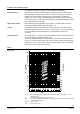
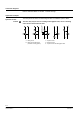
Sizing
4741D01
D
N
1
5
k
V
S
0
,
6
D
N
1
5
k
V
S
1
,
5
V
100
[l/s]
Χ
pmax
Χ
p
V100
V
100
[m
3
/h]
Χp
V
100 = differential pressure across the fully open valve and the valve’s control path 1 ↑ 3 by a
volumetric flow V
100
V
100
= volumetric flow through the fully open valve (H
100
)
Χpmax = max. permissible differential pressure across the valve’s control path for the entire actuating
range of the motorised valve
100 kPa = 1 bar ≡ 10 mWC
1 m
3
/h = 0.278 l/s water at 20 °C
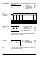
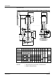
Control operation
Spring return facility
Control
Manual operation
Flow chart