
Installation Instructions

Document No. 565-548
Installation Instructions
November 15, 2006
• Cabling and co
nnectors. See the Connecting
the Y OR K ISN En
hanced Driver to the YORK
System sectio
n.
CAUTION:
Always wear a
n electro-static discharge
wrist strap a
nd discharge accumulated
static befor
etouchingfield panel
components.
Prerequisi
tes
• Driver hardware is installed according to its
respective installa tio n instructions.
• FLN Termination blocks installe d, if any.
• One 115V or 2
30V receptacle (depending on
device) to p
ower the Trunk Inte rface II.
Dependingont
he type of installation, other
prerequisite
s may have to be completed.
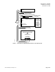
Connecting the YORK ISN
Enhanced Driver to the YORK
System
Follow these steps to connect the YORK ISN
Enhanced Driver to the YORK system:
1. Make cables per diagram in Figure 1.
2. Install the Trunk Interface II per diagram in
Figure 1.
3. Connect cables per diagram in Figure 1.
4. Plug in power
supply for the Trunk Interface II per
diagram in F
igure 1.
P
age 2 of 4
S
iemens Building Technologies, Inc.