
Installation Instructions

Document No. 565-981
Installation Instructions
June 1, 2007
Required Tools and Materials
• Flat-blade screwdriver (1/8-inch blade width).
• Wire strippers.
• Cabling and connectors. See the Connecting
the Trane Enhanced 2000 Driver to the Trane
System section.
CAUTION:
Always wear an electro-static discharge
wrist strap and discharge accumulated
static before touching field panel
components.
Prerequisites
• Driver hardware is installed according to its
respective installation instructions.
• FLN Termination blocks installed, if any.
• One 115V or 230V receptacle (depending on
device) to power the Trunk Interface II.
Depending on the type of installation, other
prerequisites may have to be completed.
Connecting the Trane Enhanced
2000 Driver to the Trane System
Follow these steps to connect the Trane Enhanced
2000 Driver to the Trane system:
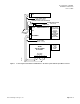
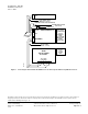
1. Make cables per diagram in Figure 1 or Figure 2.
2. Install the Trunk Interface II per diagram in
Figure 1 or Figure 2.
3. Connect cables per diagram in Figure 1 or
Figure 2.
4. Plug in power supply for the Trunk Interface II per
diagram in Figure 1 or Figure 2.
Page 2 of 4 Siemens Building Technologies, Inc.