
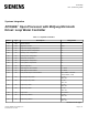
Data Sheet for Product

Information in this document is based on specifications believed correct at the time of publication. The right is reserved to make changes as design
improvements are introduced. Other product or company names mentioned herein may be the trademarks of their respective owners.
© 2002 Siemens Building Technologies, Inc.
Siemens Building Technologies, Inc. Printed in the U.S.A.
1000 Deerfield Parkway Document No. 127-0015
Buffalo Grove, IL 60089-4513 Page 6 of 6
U.S.A.
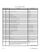
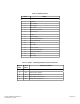
Table 5. Alarms – Problem Conditions (Points 24 and 25).
Value
If Clear
Value If
Active
Problem Condition Action Controller Takes
29 157 Tower Pump 1 in Manual Set Pump Select to Tower Pump 1
30 158 Tower Pump 2 in Manual Set Pump Select to Tower Pump 2
31 159 Boiler Pump 1 in Manual Set Boiler Select to Boiler Pump 1
33 161 Boiler Pump 2 in Manual Set Boiler Select to Boiler Pump 2
34 162 Loop Pump 1 in Manual Set Loop Select to Loop Pump 1
35 163 Loop Pump 2 In Manual Set Loop Select to Loop Pump 2
36 164 Low Tank Temperature Sound Alarm
37 165 Loop Freeze Start LWC if Off
38 166 Low Loop Temperature Sound Alarm
39 167 High Loop Temperature Sound Alarm
40 168 Tower Pump 1 Fail Start Pump 2
49 177 Tower Pump 2 Fail Start Pump 1
50 178 Boiler Pump 1 Fail Start Pump 2
51 179 Boiler Pump 2 Fail Start Pump 1
52 180 Loop Pump 1 Fail Start Pump 2
53 181 Loop Pump 2 Fail Start Pump 1
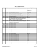
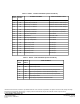
Table 6. Alarms – Fault Conditions (Points 24 and 25).
Value If
Clear
Value If
Active
Fault Condition
54 182 Tower Pumps Failed
55 183 Boiler Pumps Failed
56 184 Low Loop Temperature. Lockout Heat Pump Compressors.
57 185 High Loop Temperature. Lockout Heat Pump Heating.
58 186 High Loop Temperature. Lockout Heat Pump Compressors.
59 187 Loop Pumps Failed
60 188 Loop Supply Temperature Thermistor Failed