
Data Sheet for Product

Page 4 of 8 Siemens Building Technologies, Inc.
Document No. 127-0025
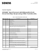
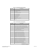
Table 2. Unit Status (Point 03).
Value Description
0 Off – Manual Set Point
1 Off – S-1 Switch. System switch is in stop position.
2 Off—System Communication
3 Off – Remote Switch. Chiller commanded off via the
network.
4 Off – Time Schedule. The time schedule indicates an
off time period.
5 Off – Compressor 1 or 2 Fault (Alarms). Condition
exists that prevents normal operation. Chiller disabled.
6 Off – Pump-down Switches PS-1 and PS-2. Chilled
water requirements met. Compressors unload. Liquid
line solenoid valves are de-energized. Condenser fans
shut off.
7 Off – Ready To Start. Only when none of states 1 – 6
are true.
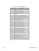
8 Starting
9 Waiting for Flow. Chiller enabled. Remains in this state
until chilled water is detected in field installed flow
switch.
10 Waiting for Load. Once water is detected, controls
sample the chilled water and compare it against leaving
chilled water set point. If chiller water temperature is
greater than set point, the chiller is enabled to run.
11 Cooling Stage-up. Chilled water is above set point.
12 Cooling Stage-down. Chilled water is below set point.
13 Cooling Staging
14 Manual Cooling Staging