
Installation Instructions

Document No. 565-003
Installation Instructions
September 9, 2009
FLN 1
DRIVER
S
+
-
S
-
+
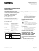
RS-485 TRUNK CABLE
(MAX 4000’ / 1219.2 m;
STANDARD 24 AWG LOW CAPACITANCE)
BLUE RIDGE
TECHNOLOGIES PANEL
RS-485 CONNECTOR
(SEE EXPLODED VIEW)
TAPE BACK
SHIELD
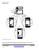
GW1520R1
PROGRAMMABLE
SWITCH INPUTS
RS-485
MODULE
ON
MAIN BOARD
RS-485
TRUNK
CONNECTOR
(SERIAL)
LED’s
SERIAL
1 2 3 4 5 6 7 8 9 10 11 12 13 14 15 16
17 18 19 20 21 22 23 24
1 2 3 4 5 6 7 8 9 10 11 12 13 14 15 16
17 18 19 20 21 22 23 24
CPU
BOARD
PROGRAMMABLE
SWITCH INPUTS
RS-485
CONNECTOR
(SERIAL)
1 2 3 4 5 6 7 8 9 10 11 12 13 14 15 16
17 18 19 20 21 22 23 24
LX5
CPU
BOARD
1 2 3 4 5 6 7 8
RS-485 TRUNK CABLE
(MAX 4000’ / 1219.2 m;
STANDARD 24 AWG
LOW CAPACITANCE)
TO ADDITIONAL
BLUE RIDGE
TECHNOLOGIES
PANELS
ANALOG
INPUTS
NODE NUMBER
DIAL SWITCHES
CONFIGURATION
SWITCHES
MAXIOM LX5
BOARD
LEGACY PANELS
UPGRADED STYLE
LEGACY PANELS
OLD STYLE WITH
PIGGY-BACKED
RS-485 BOARD
PROGRAMMABLE
SWITCH INPUTS
RS-485
MODULE
PIGGYBACKED
ONTO
MAIN BOARD
RS-485 TRUNK
CONNECTOR (J8)
LED’s
MOUNTING
SCREWS
CPU
BOARD
The installation is now complete.
Information in this publication is based on current specifications. The company reserves the right to make changes in specifications and
models as design improvements are introduced. APOGEE is a registered trademark of Siemens Industry, Inc. Other product or company
names mentioned herein may be the trademarks of their respective owners. © 2009 Siemens Industry, Inc.
Siemens Industry, Inc.
Building Technologies Division
1000 Deerfield Parkway
Buffalo Grove, IL 60089-4513
U.S.A.
Your feedback is important to us. If you have
comments about this document, please send them
to SBT_technical.editor.us.sbt@siemens.com
Document No. 565-003
Printed in the USA
Page 2 of 2