
Installation Instructions

Document No. 565-906
Installation Instructions
August 15, 2009
Connecting the Barber-Colman
Network 8000 Enhanced Driver to
the Barber-Colman System
Follow these steps to connect the Barber-Colman
Network 8000 Enhanced Driver to the Barber-Colman
system:
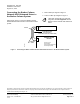
1. Make cables per diagram in Figure 1.
2. Connect cables per diagram in Figure 1.
LCM block functionality and LCM bus
integration are not supported with the
Barber-Colman Network 8000 Enhanced
Driver.
FLN
DRIVER
+
-
S
-
+
BARBER-COLMAN
DEVICES
MicroZone II (MZ II)
MicroFlo II (MF II)
Package Equipment Module (PEM)
MicroNet Integrator (ASDI)
TAPE BACK
SHIELD
GW1341R1
RS-485 TRUNK CABLE
(MAX 4000’/1200 m;
STANDARD 24 AWG LOW CAPACITANCE)
ASD Bus
Figure 1. Connecting the Barber-Colman Network 8000 Enhanced Driver to the Barber-Colman System.
Information in this document is based on specifications believed correct at the time of publication. The right is reserved to make changes as
design improveme nts are introd uce d. Product or company names mentioned herein may be the trademarks o f their respective owners.
© 2009 Siemens Building Technologies, Inc.
Siemens Building Technologies, Inc. Your feedback is important to us. If you have Document No. 565-906
1000 Deerfield Parkway comments about this document, send them to Country of Origin: US
Buffalo Grove, IL 60089-4513 SBT_technical.editor.us.sbt@siemens.com.
Page 2 of 2
U.S.A.