
Installation Instructions

Document No. 550-695
Installation Instructions
Rev. 1, May, 2002
Page 4 of 11
Siemens Building Technologies, Inc.
Terminal Designations
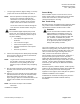
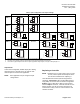
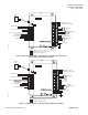
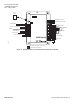
Figure 4 shows the LTEC wiring designations and
internal jumper locations for both controllers.
NOTE: All inputs and outputs physical connections are
pre-configured per application number
selected.
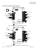
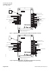
The wiring diagrams (Figure 5 through
Figure 11) are shown using the full point
controllers (shaded terminals). Reduced point
controllers should be used when the additional
input/output points are not required.
LON0018R2
1
2
3
4
5
6
AI/DI 1
AI/DI 2
5V
+
-
5V
+
-
1
2
3
4
5
6
7
+
-
+
-
5V
+
-
AI/DI 3
AI/DI 5
J4
J13
J12
J6
AI/DI 4
Figure 4. Terminal Designations.
Input Ports
LTECs have configurable, flexible input ports. Table 1
lists each input port and indicates the input options
available for that port.
NOTE: Some models have only the first four inputs,
while others have five inputs. (Only VAV
models have the integral flow sensor port).
Table 1. LTEC Input Port Configuration Options.
Input Type/Number Configurable Options Notes
RJ-11 input jack Temperature sensor
Set point adjustment
Override button
550-180 thru 187 wall modules
AI/DI 1 Digital Input or
Temperature Input
100K thermistor
AI/DI 2 Digital Input or
Temperature Input
100K thermistor
AI/DI 3 Digital Input or
Voltage Input or
Temperature Input
0-10Vdc or
0-20/4-20 mA
AI/DI 4 Digital Input or
Voltage Input or
Temperature Input
0-10Vdc or
0-20/4-20 mA
AI/DI 5 Digital Input or
Voltage Input or
Temperature Input
0-10Vdc or
0-20/4-20 mA
Integral Flow Sensor Flow Input VAV/CV only