
Installation Instructions

Document No. 550-695
Installation Instructions
Rev. 1, May, 2002
Page 2 of 11
Siemens Building Technologies, Inc.
Required Tools
• Pencil
• ESD wrist strap
• Small flat blade screwdriver
• Medium flat blade screwdriver
• Wire stripper
• Medium duty electric drill
• ¼ in (6mm) hex nut bit
• Network Management Tool
• Bus interface and cables
Prerequisites
• Room temperature sensor (RTS), if required, is
installed
• Airflow pickup assembly is properly installed in
the supply duct
• Power source of 24 Vac, 60 Hz Class 2 power
trunk is available and has a sufficient VA rating
for the controller, sensors and actuators
• If required, the controller enclosure is installed
• Power supply to the unit is OFF
WARNING:
The power must be turned OFF prior to
wiring the unit.
Installation
The following sections are included in these instructions:
• Controller Mounting
• Power Wiring
• Bus Wiring
• Replacing a Controller
Controller Mounting
1. Using the controller as a template, position the
controller vertically and mark the mounting-hole
locations on the mounting surface (terminal box or
mounting enclosure).
2. Using the #6 self-tapping screws (included), fasten
the controller to the terminal box or enclosure.
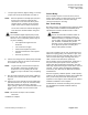
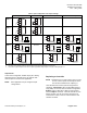
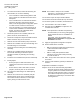
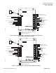
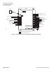
3. Connect the LonWorks Network (NOT polarity
sensitive) cable to terminals 1 and 2 on J2 (NET)
(Figure 3).
1
2
1
2
3
4
5
6
1
2
3
4
5
6
7
1
2
3
4
5
6
1
2
3
4
5
6
7
8
9
10
11
12
13
14
15
16
N
H
E
5V
+
-
5V
+
-
+
A01
+
A02
+
A03
D01
D02
D03
D04
D05
D06
D07
D08
+
-
+
-
5V
+
-
NMT
RTS
SRV
BST
SRV
BST
NET
DI1
AI1/
DI2
AI2/
DI2
AI2/
DI3
AI3/
DI4
AI4/
DI5
AI5/
-
-
-
24Vac H
24Vac H
24Vac H
24Vac H
24Vac H
24Vac H
24Vac H
24Vac H
24Vac H
Neutral
EGrnd
LON0007R1
J6
J4
Not available on reduced point controller boards.
J2
J7
J3
J1
Analog
Output
Mounting Holes (4)
Cover Release Tabs
Digital
Output
Air Velocity Sensor
Connections (LO above HI)
24 Vac Power
Analog
or Digital
Input
Network
Trunk
Service Pin
Room Temperature
Sensor Connection
Network Management
Tool Connection
Only available on Unit Vent Controller.
Figure 3. LTEC Wiring Designations.
4. With primary power disconnected, connect 24vac
power to terminal block J1.
5. Connect the ‘EGrnd’ terminal (E) to an earth
ground.
NOTE: A proper ground source is required (to
protect the electronic circuits) for
example; a cold water pipe, power panel
ground (green wire) or other comparable
ground sources.
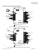
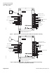
6. Connect the input and output wiring for the
appropriate VAV (Variable Air Volume) or CV
(Constant Volume) application. Refer to the
Terminal Designations section for complete
information on LTEC wiring designations for both
the 550-530 and the 550-532 controllers.