
Installation Instructions

Document No. 550-695
Installation Instructions
Rev. 1, May, 2002
Page 10 of 11
Siemens Building Technologies, Inc.
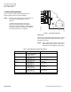
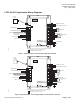
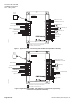
Not available on reduced point controller boards.
J2
J7
J3
J1
Network Trunk
Sensor Source Temp 100 K
Spare DI
Wall Switch DI
OCC Sensor DI
Spare PCT 0-10 Vdc
Jumper
Damper Act. 0-10 Vdc
Terminal Htg. Coil 0-10 Vdc
Damper Act.
1
2
1
2
3
4
5
6
1
2
3
4
5
6
7
1
2
3
4
5
6
1
2
3
4
5
6
7
8
9
10
11
12
13
14
15
16
N
H
E
5V
+
-
5V
+
-
+
A01
+
A02
+
A03
D01
D02
D03
D04
D05
D06
D07
D08
+
-
+
-
5V
+
-
NMT
RTS
SRV
BST
SRV
BST
NET
DI1
AI1/
DI2
AI2/
DI2
AI2/
DI3
AI3/
DI4
AI4/
DI5
AI5/
-
-
-
24Vac H
24Vac H
24Vac H
24Vac H
24Vac H
24Vac H
24Vac H
24Vac H
24Vac H
Neutral
EGrnd
LON8033WDR1
Terminal Htg.
Coil
Perimeter Htg.
Coil
Spare -1 DO
Perimeter Htg. DO
Room
Sensor
24 Vac Power
Ground
J6
J4
Only available on Unit Vent Controller.
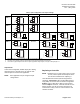
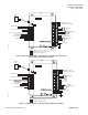
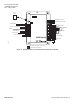
Figure 11. Application 8033 - CV with Hot Water Heat (550-530 or 550-532).