
Installation Instructions

Installation Instructions
Document No. 550-695
Rev. 1, May, 2002
LTEC VAV/CV
Single Duct DDC Controller
Page 1 of 11
Product Description
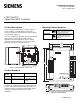
These instructions explain how to install or replace a
LTEC (LonMark
Terminal Equipment Controller)
VAV/CV (Variable Air Volume/Constant Volume) Single
Duct Controller (Figure 1).
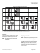
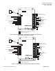
There are two platforms available, reduced point and full
point (Figure 3); each platform handles various
application sets. Each application set has a default
input/output-wiring configuration, shown in the wiring
diagrams. See Figure 5 through Figure 11.
LON0006R1
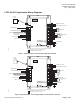
Figure 1. LTEC Controller – open cover.
Product Numbers
Part
Number
Application Input/Output
550-530 VAV/CV Single Duct 4 IN, 6 DO, 1 DPS
550-532 VAV/CV Single Duct 5 IN, 8 DO, 2 AO,
1 DPS
In addition to the listed inputs above, each platform can
accept a series 550-180 through 550-187 LTEC room
temperature sensor (RTS) with optional digital display,
occupancy override push button and set point
adjustment.
Warning/Caution Notations
WARNING
Personal injury/loss of life may
occur if a procedure is not
performed as specified.
CAUTION
Equipment damage, or loss of
data may occur if the user
does not follow procedure as
specified.
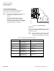
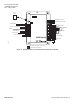
LON0034R1
8 7/8"
(2.25mm)
8 1/16"
(205mm)
1 7/8"
(48mm)
LO
HI
5"
(127mm)
6 3/16"
(157mm)
1
2
1
2
3
4
5
6
1
2
3
4
5
6
7
1
2
3
4
1
2
3
4
5
6
7
8
9
10
11
12
13
14
15
16
N
H
E
5V
+
-
5V
+
-
+
A01
+
A02
D01
D02
D03
D04
D05
D06
D07
D08
+
-
+
-
5V
+
-
NMT
RTS
SRV
BST
SRV
BST
NET
DI1
AI1/
DI2
AI2/
DI2
AI2/
DI3
AI3/
DI4
AI4/
DI5
AI5/
-
-
24Vac H
24Vac H
24Vac H
24Vac H
24Vac H
24Vac H
24Vac H
24Vac H
24Vac H
Neutral
EGrnd
J6
J4
J2
J7
J3
J1
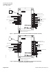
Figure 2. LTEC Controller.