
Installation Instructions

Document No. 550-696
Installation Instructions
Rev. 1, May, 2002
Page 6 of 9
Siemens Building Technologies, Inc.
1. To record Initial Values, before disconnecting the
old controller, do one of the following:
• If the controller is communicating with the field
panel, update the controller initial values at the
field panel.
• If the controller does not communicate with the
field panel, but does communicate with the
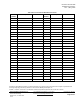
NMT, record the appropriate configuration points
on Table 3 at the end of these instructions.
• If the old controller is not communicating at all,
record all data available in the Point Definition
Report, or from the last valid initial values
uploaded from the controller.
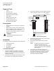
2. Disconnect power to the controller (remove the
power connector, terminal block J1).
3. Disconnect all input and output removable terminal
blocks and insure they do not short out.
4. Remove the RTS and network (RJ11) connectors.
5. Remove the controller board by pressing the
internal tabs and lifting the board out (or the
complete controller, by removing the mounting
screws).
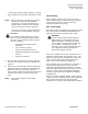
6. Install the new controller board (or base and board).
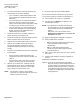
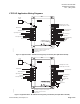
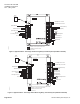
7. Install jumpers.
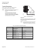
• Ensure jumpers for AI/DI 3 and AI/DI 4 are
configured to match the removed controller, see
Table 2.
• Ensure AI/DI 1, AI/DI 2 and AI/DI 5, external
jumpers, remain in place or are reinstalled.
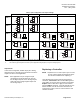
8. Remove one of the Neuron
ID labels (two part
label located at the top of the controller board).
Record this number as directed; on a floor plan
layout, job log or inside the RTS cover.
NOTE: This number is unique to the controller
electronics. It is imperative that the old neuron
label be removed or covered.
9. Reconnect input and output terminal blocks.
10. Reconnect RTS and network (RJ-11) connectors.
11. Reconnect power to controller, terminal block J1.
12. Connect NMT to the LTEC or L model MEC.
13. Run NMT and use Replace to replace the old
controller with new one.
NOTE: If the replacement controller was previously
used elsewhere (not in factory packaging) the
factory defaults must be re-established as
follows:
Using NMT, select the controller, select
Application Configuration and apply the Set
to Defaults command.
14. Apply the appropriate Configuration Template.
15. Restore initial values as follows:
• MMI: If a field panel update was performed, the
LTECs initial values will be loaded
automatically.
• NMT: If a field panel update was NOT
performed, set the initial values previously
recorded in Table 3.
16. NMT: Verify LTEC Connections are correct, update
as needed.
17. Save the peak database (.pkd file) to flash/file as
needed.
Replacement installation is complete.
Disposal As an aid to environmentally responsible
disposal, the larger plastic components bear a
recycle symbol. The controller should not be
disposed of with domestic waste. The printed
circuit board and plastic components should
be disposed of separately in accordance with
local regulations.