
Installation Instructions


Document No. 550-696
Installation Instructions
Rev. 1, May, 2002
Siemens Building Technologies, Inc. Page 3 of 9
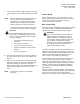
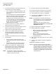
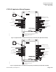
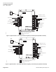
7. For input type selection, (digital, voltage, or current)
see the jumper and connection information in Table
2.
NOTE: Each DO provides a normally open (NO) and
24 Vac hot (H) terminal. Terminate both
connections of a 24 Vac load directly to the
controller board. Floating control actuators
require 2 DOs and use 3 wire connections.
The 24 Vac Common is switched through the
Triac when the associated DO is energized.
CAUTION:
The controllers Digital Outputs (Dos) control
24 Vac only. The maximum rating is 12 VA for
each DO. Use an interposing 24Vac relay for
any of the following:
• VA requirements higher than the
maximum
• 110 or 220 Vac or higher
• Control load requires DC power
• Separate transformers used to power
the load
• Need for dry contacts
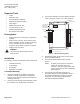
8. Plug the room temperature sensor (RTS) cable into
the ‘RTS’ port on the left side of the controller. See
Figure 2.
9. Remove one of the controller neuron ID labels (two
part label located at the top of the controller board).
Record this number as directed in a floor plan
layout, job log or place the self-adhesive label on the
outside of the controller case or inside the RTS
cover.
NOTE: This number is unique to the controller
electronics.
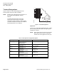
Power Wiring
Each Controller requires a source of 24 Vac, 60 Hz
Class II power supply. The base rating of the controller
and the sum of the sensor, actuators and relay
connected dictates the VA rating.
Bus Trunk wiring
Bus wiring must be accomplished using approved cables
only. These include unshielded and shielded (where
specified) two conductor 22 AWG Level IV cable.
WARNING:
Use the recommended LonWorks cable: 22
AWG shielded or unshielded, Level IV per
NEMA standards (not equivalent to EIA/TIA
Level 4 cable). Connect Air brand cable, 22/1
pair, stranded, unshielded, blue plenum
jacketed, Level IV, Part Number W221P-2001
or an approved equal for bus wiring. Bus
wiring is NOT polarity sensitive.
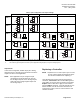
The LTEC Controllers use the FTT-10 transceiver that
allows free topology wiring. This includes T-taps, stars,
branches, loops as well as standard daisy chain. In all
cases, max bus wire length, including each sensor
cable, cannot exceed 500 meters (1640 feet).
For bus lengths that exceed 500 meters, (1640 feet) a
two-port or three-port repeater can be used (Part
number 587-450 and 587-455 respectively). This will
allow three separate bus lengths of 500 meters. See the
LonTalk
Two and Three Port Repeater installation
instructions, (P/N: 550-310) for additional information
and limitations.
Each bus segment (1 without repeater, 3 with repeater)
requires a pair of terminating resistors (Part number 587-
649 – packs of 100) that can be located together
anywhere on the segment, at the field panel or repeater.