
Installation Instructions

Installation Instructions
Document No. 550-697
Rev. 1, May, 2002
LTEC Unit Ventilator
DDC Controller
Siemens Building Technologies, Inc. Page 1 of 10
Product Description
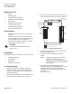
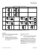
These instructions explain how to install or replace a
LTEC (LonMark
Terminal Equipment Controller) UV
(Unit Vent) DDC Controller (Figure 1). Each platform
supports various applications of the Unit Vent terminal
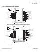
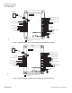
unit. Each application set has a default input / output
wiring configuration shown in Figure 5 through Figure 9.
The LTEC UV DDC Controller applications are provided
in the following configurations:
• UVC- Unit Vent Chill Water, w/single speed fan,
2 or 4 pipe heating and/or cooling coils, outside
air damper control.
• UVD- Unit Vent – DX, w/single speed fan,
single or multi stage DX cooling, terminal
heating coils, outside air damper control.
• UVF- Unit Vent – Face & Bypass damper
control, 2 or 4 pipe cooling and/or heating coils,
outside air damper control.
LON0006R1
Figure 1. LTEC Controller – open cover.
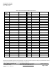
Product Number
Part
number
Application Input/Output
550-540 LTEC UVC CW/HW 2/4 pipe 4 IN, 6 DO
550-542 LTEC UVC CW/HW 2/4 pipe 5 IN, 8 DO, 3 AO
550-541 LTEC UVD DX w/htg. 4 IN, 6 DO
550-543 LTEC UVD DX w/htg. 5 IN, 8 DO, 3 AO
550-544 LTEC UVF w/Face/Bypass w
2/4 pipe htg/clg
5 IN, 8 DO, 3 AO
In addition to the listed inputs above, each platform can
accept a series 550-180 through 550-187 LTEC room
temperature sensor (RTS) with optional digital display,
occupancy override push button and set point
adjustment.
Warning/Caution Notations
WARNING
Personal injury/loss of life may
occur if a procedure is not
performed as specified.
CAUTION
Equipment damage, or loss of
data may occur if the user
does not follow procedure as
specified.
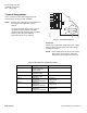
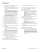
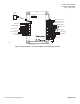
LON0026R1
8 7/8"
8 1/16"
1 7/8"
LO
HI
5"
6 3/16"
1
2
1
2
3
4
5
6
1
2
3
4
5
6
7
1
2
3
4
5
6
1
2
3
4
5
6
7
8
9
10
11
12
13
14
15
16
N
H
E
5V
+
-
5V
+
-
+
A01
+
A02
+
A03
D01
D02
D03
D04
D05
D06
D07
D08
+
-
+
-
5V
+
-
NMT
RTS
SRV
BST
SRV
BST
NET
DI1
AI1/
DI2
AI2/
DI2
AI2/
DI3
AI3/
DI4
AI4/
DI5
AI5/
-
-
-
24Vac H
24Vac H
24Vac H
24Vac H
24Vac H
24Vac H
24Vac H
24Vac H
24Vac H
Neutral
EGrnd
J6
J4
J2
J7
J3
J1
Figure 2. LTEC Controller.