
Installation Instructions

Document No. 550-598
Installation Instructions
Rev. 1, May, 2002
Page 8 of 10
Siemens Building Technologies, Inc.
Not available on reduced point controller boards.
J2
J7
J3
J1
Network Trunk
Spare DI
Spare Temp Sensor
Fan Status DI
OCC Sensor DI
Spare Input 0-10 Vdc
Spare AO 0-10 Vdc
Perimeter Htg. Coil 0-10 Vdc
Perimeter Htg. Coil
1
2
1
2
3
4
5
6
1
2
3
4
5
6
7
1
2
3
4
5
6
1
2
3
4
5
6
7
8
9
10
11
12
13
14
15
16
N
H
E
5V
+
-
5V
+
-
+
A01
+
A02
+
A03
D01
D02
D03
D04
D05
D06
D07
D08
+
-
+
-
5V
+
-
NMT
RTS
SRV
BST
SRV
BST
NET
DI1
AI1/
DI2
AI2/
DI2
AI2/
DI3
AI3/
DI4
AI4/
DI5
AI5/
-
-
-
24Vac H
24Vac H
24Vac H
24Vac H
24Vac H
24Vac H
24Vac H
24Vac H
24Vac H
Neutral
EGrnd
LON8052WDR1
Terminal Fan Relay
Room
Sensor
24 Vac Power
Ground
2
Perimeter Htg. DO
DX Stage 1 Clg.
1
3
J6
J4
Only available on Unit Vent Controller.
Jumper
Terminal
Staged
Heat
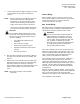
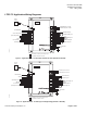
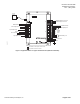
Figure 7. Application 8052 - FC-DX with Electric Heat (550-535 or 550-537).
Not available on reduced point controller boards.
J2
J7
J3
J1
Network Trunk
Spare DI
Spare Temp Sensor
Fan Status DI
OCC Sensor DI
Spare Input 0-10 Vdc/4-20 ma
Terminal Htg. Coil 0-10 Vdc
Perimeter Htg. Coil 0-10 Vdc
1
2
1
2
3
4
5
6
1
2
3
4
5
6
7
1
2
3
4
5
6
1
2
3
4
5
6
7
8
9
10
11
12
13
14
15
16
N
H
E
5V
+
-
5V
+
-
+
A01
+
A02
+
A03
D01
D02
D03
D04
D05
D06
D07
D08
+
-
+
-
5V
+
-
NMT
RTS
SRV
BST
SRV
BST
NET
DI1
AI1/
DI2
AI2/
DI2
AI2/
DI3
AI3/
DI4
AI4/
DI5
AI5/
-
-
-
24Vac H
24Vac H
24Vac H
24Vac H
24Vac H
24Vac H
24Vac H
24Vac H
24Vac H
Neutral
EGrnd
LON8053WDR1
Terminal Fan Relay
Room
Sensor
24 Vac Power
Ground
Terminal Htg. Coil
DX Stage 1 Clg.
Perimeter Htg.
Coil
Spare DO
Space Lights DO
J6
J4
Only available on Unit Vent Controller.
Jumper
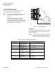
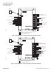
Figure 8. Application 8053 - FC-DX with Hot Water Heat (550-535 or 550-537).