
User Manual


6/18
Building Technologies Division CC1N7495en
20.04.2016
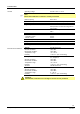
Technical data (cont’d)
Total current of all mains components
connected to the LMU7... and the ClipIns
5 A (at UN = AC 230 V; Tu = 60 °C)
Mains extension (X1-02)
- Voltage
- Current
AC 230 V +10 % / -15 %
Depending on power consumption heating
circuit pump, programmable AC 230 V
output, fuel valve, DHW charging pump,
external ignition transformer and used
ClipIn
AC 230 V fan (X2-01)
- Voltage
- Current
AC 230 V +10 % / -15 %
Depending on used fan
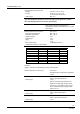
K1 (X2-02)
- Voltage
- Current
AC 230 V +10 % / -15 %
5 mA…1 A, cos >0.8
K2 (X2-03)
- Voltage
- Current
AC 230 V +10 % / -15 %
5 mA…1 A, cos >0.8
K3 (X2-04)
- Voltage
- Current
AC 230 V +10 % / -15 %
5 mA…1 A, cos >0.8
Flame supervision / ionization probe (X2-
05)
- Switching thresholds
- Current
- Response time in the event of loss of
flame
- Touching
- Cable length of flame detector
Min. 0.8 µA (required DC)
Typical 1.6 µA
Max. 2.4 µA
<1 s
Not permitted
1 m
Safety limiter (X3-01)
- Voltage
- Current
AC 230 V +10 % / -24 %
5 mA…1 A, cos > 0.6
carrying power supply for fuel valve and
ignition
Fuel valve (X3-02)
- AC output
- Current
AC 230 V +10 % / -24 %
valve must still open at AC 175 V
5 mA…0.5 A, cos > 0.8
Note:
Fuel valves with rectifier may be connected to the fuel valve output only after consulta-
tion with Siemens! In that case, additional protective measures inside the LMU7… are
required (optional PCB).
RAC output
- Pmax
RAC 230 V +10 % / -15 %, 100 Hz
valve must still open at AC 175 V
20 W, cos > 0.9
General data for fuel valve connection
- Cable length
- Leak current at 1.06 x rated voltage
- Capacitive extra circuitry or surge
voltage limiting protective elements
Max. 3 m
Max. 0.5 mA
Not permitted
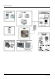
Electrical
connections