
User Manual


17/18
Building Technologies Division CC1N7495en
20.04.2016
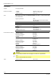
Basic diagram (cont'd)
Lockout
(STB, TB)
Safety
shutdown (GP)
Boiler flow sensor
(tested)
Boiler return sensor
(tested)
DHW sensor 1
or
DHW thermostat
Outside sensor
Room thermostat 1
or time switch
BV2
BV1
external
ignition module
Heating circuit pump
DHW pump 1
or
diverting valve
4
modulated
PWM fan
AC 230 V
LMU75...
Water pressure sensor
Heating circuit
pressure switch
Programmable digital
input e.g. for
air pressure switch
6
Stepper motor
control
(combustion
optimization)
M
AC 230 V
AC 230 V
Room controller
Operator unit
2 / 3
Programmable
output
Fuel valves
RAC 26 V
AC 230 V
RAC 26 V
RAC 26 V
RAC 26 V
RAC 26 V
DHW FlowSwitch
or
DHW thermostat
HMI
AVS37...
AC 230 V
AC 230 V
or
RAC 230 V
AC 230 V
Room thermostat 2
or time switch
RAC 26 V
Reset button
QAA55... QAA75...
5
AGU2.5... ClipIn
The diagram shows the full scope of functions offered by the LMU75… system. The ac-
tual functions are to be determined based on the respective execution / configuration.