
User Manual


8/9
Building Technologies Division CC1N7494en
20.04.2016
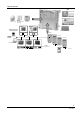
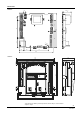
Basic diagram
Lockout (SLT, LT)
Safety shutdown (GP)
Boiler flow sensor (tested)
Boiler return sensor (tested)
DHW sensor 1 or
DHW thermostat
Outside sensor
Room thermostat or
time switch
BV2
BV1
Ignition module
Heating circuit pump
DHW pump1 or
diverting valve
4
Modulated PWM fan
AC 230 V or DC 24 V
LMU5...
LMU6...
Water pressure sensor
Heating circuit
pressure switch
Programmable digital input
(e.g. for air pressure switch)
Ignition module integrated
PWM / hall
6
Stepper motor control
(diverting valve)
M
AC 230 V
PWM modulated
AC 230 V
Room controller QAA73
QAA53
Operating unit
2
ION
Flame supervision (continuous)
Programmable output
Flue gas sensor /
DHW sensor 2
Fuel valves
Stepper motor control
(diverting valve)
M
P
RAC 26 V
AC 230 V
RAC 26 V
RAC 26 V
RAC 26 V
RAC 26 V
DHW flow switch or
DHW thermostat
HMI
AGU2.3...
AC 230 V
AC 230 V
or
RAC 230 V
AC 230 V
NTC 10 k
NTC 10 k
NTC 10 k
NTC 1 k
NTC 10 k
7494a01e/0906
4
The diagram shows the full scope of functions of the LMU5… / LMU6… system. The
actual functions are to be determined based on the respective execution / configuration.