
User Manual


5/9
Building Technologies Division CC1N7494en
20.04.2016
Technical data (cont’d)
Total current, all mains components con-
nected to the LMU5… / LMU6... and the
ClipIns
5 A (at UN = AC 230 V; Tu = 60 °C)
Safety temperature limiter
- Voltage
- Current
AC 230 V +10 % / -24 %
5 mA…1 A, cos > 0.6
carrying power supply for fuel valve and
ignition
Fuel valve
- AC output
- Current
AC 230 V +10 % / -24 %
valve must still open at AC 175 V
5 mA…0.5 A, cos > 0.8
5 mA…0.2 A, cos > 0.6
Note!
Fuel valves with rectifier may be connected to the fuel valve output only after consulta-
tion with Siemens! In that case, additional protective measures inside the LMU5… /
LMU6… are required (optional PCB).
RAC output
- Pmax
RAC 230 V +10 % / -15 %, 100 Hz
valve must still open at AC 175 V
20 W, cos > 0.9
General data for fuel valve connection
- Cable length
- Leak current at 1.06 x rated voltage
- Capacitive extra circuitry or surge
voltage limiting protective elements
Max. 3 m
Max. 0.5 mA
not permitted
External ignition module
- Voltage
- Current
- Cable length
AC 230 V +10 % / -15 %
5 mA…0.5 A, cos > 0.8
must still ignite at AC 175 V
Max. 3 m
Any external ignition modules used must be approved by Siemens to ensure
their switching performance meets the requirements!
Integrated ignition module
- Ignition power / pulse
- Pulse sequence
- Touching
- No-load voltage
- No-load operation
min. 3 mJ, 2 k
Max. 4 mJ, 2 k
in the range of AC 175…153 V
min. 10 Hz at AC 175 V
Max. 25 Hz at AC 253 V
not permitted
20 kV
Max. 30 s
Fan control
- Current draw
- Cable length
Max. DC 1.2 A
(on applications with stepper motor con-
trol for combustion optimization and DHW
diverting valve)
Max. DC 1.5 A
(on applications without stepper motor
control for combustion optimization and
DHW diverting valve)
3 m
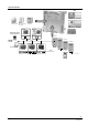
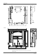
Electrical connections