
User Manual


5/32
Building Technologies Division CC1N7491en
18.07.2018
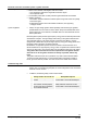
Electrical connection of ionization probe or ignition electrode
It is important to achieve practically disturbance- and loss-free signal transmission:
∂ Never run the detector cable together with other cables
– Line capacitance reduces the magnitude of the flame signal
– Use a separate cable
∂ The ionization probe does not offer protection against electrical shock hazard
∂ Isolation resistance
- The isolation resistance between ionization probe and ground reduce the quantity
of the flame signal
- Soiled detector holders reduce the isolation resistance, thus supporting
creepage currents
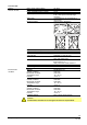
∂ Always run high-voltage ignition cables separately while observing the greatest
possible distance to the unit and to other cables. Always use suitable cable for the
ignition equipment. If not observed, unsuitable cable can cause electrical shock or
lead to plant failure
Electrical ignition sparks produce high-frequency energy that can adversely affect radio
and television reception. The high-voltage cable running to the ignition electrode acts
as a transmitter antenna. The ignition module connected to the LMU34…must be
equipped with suitable filters to prevent high-frequency energy from being passed from
the ignition cable to the other connection terminals.
Nevertheless, an application-specific test must be made to ensure that there is no
electrical interference. High-frequency energy is also of capacitive and inductive nature,
and not only wire-bound. This must be taken into consideration when laying the cables.
The ignition cable must meet the technical requirements of the ignition module
and must be run to the ignition electrode as directly as possible, without any
loops.
The ignition cable must never be run parallel or very close to other electrical cables.
To avoid poor EMC performance, run the functional earth of the ignition module to
burner ground as short as possible. This wire should not be routed via the LMU34…
Commissioning notes
∂ There is no absolute protection against incorrect use of the connectors. For this
reason, prior to commissioning the plant, the correct assignment of the connection
terminals must be checked
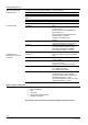
∂ In addition, the following safety checks must be made:
Safety check to be carried out Anticipated response
a) Burner start with gas valve fully
closed
Safety shutdown at the end of TSA.
Lockout after 3 unsuccessful attempts
b) Burner operation with simulated
loss of flame; for that purpose,
shut the gas valve in operation
and maintain that state
Repetition with restart, followed by
safety shutdown at the end of TSA.
Lockout after 3 unsuccessful attempts
Ionization probe
Ignition equipment