
User Manual


27/32
Building Technologies Division CC1N7491en
18.07.2018
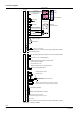
Connectors list (cont´d)
No.
Connector
type
Pin code
print on
PCB
Description LMU34.2
X401
Lumberg
MSF 10 poles
PELV: Cable length ′ 1 m
1
Flue gas temperature NTC ²) or thermostat contact
NTC 20 K at 25 °C
beta = 3970
DC 5 V
< 2 mA
2
Flue gas temperature NTC ²) or thermostat contact
NTC 20 K at 25 °C
beta = 3970
DC 5 V
< 2 mA
3 High limit thermostat (TB)
Half wave rectified
RAC 24 V
I = 2.5...5 mA
4 High limit thermostat (TB)
Half wave rectified
RAC 24 V
I = 2.5...5 mA
5
Fan interface supply GND ¹) ³)
GND
6
Fan Hall signal (fan speed) IN (non safety) ¹) ³)
2 rectangular pulses per revolution
duty ratio 1:1 +/-5 %
7
Control output PWM fan (non safety) ¹) ³)
4,800 Hz
8
Fan interface supply + ¹) ³)
DC 30 V
9 CH temperature sensor
NTC 10 kς at 25 °C
beta = 3977
DC 5 V
10 CH t emperature sensor
NTC 10 kς at 25 °C
beta = 3977
DC 5 V
X403
Lumberg 3850
4 poles
PELV: PARA-IFC (OCI425) OCI425 / ACS425
1 Internal
2 Internal
3 Internal
4 Internal
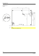
X500 Tabs 6.3 mm HT: Functional earth (burner ground) (not for protection purposes) Cable length ′ 1 m
X501 VT tabs
4.8 mm
HT: Flame (ionization probe) < AC 100 V
cable length ′ 1 m
HT: High Tension – Mains voltage connection
PELV: Protective Extra Low Voltage – Low voltage connection