
User Manual


24/32
Building Technologies Division CC1N7491en
18.07.2018
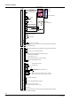
Connectors list LMU34.
No.
Connector
type
Pin code
print on
PCB
Description LMU34.2…
X1
Molex
2599 2 poles
HT: Mains supply connector
AC 230 V,
50 Hz
1 LMU34.2…: Mains supply L / L1
˜
2 LMU34.2…: Mains supply N / L2
˜
X2
Stelvio
CFM / 5 A
HT: Cable length ′ 1 m
1 Functional earth (not for protection purposes)
2 Ignition ¹) supply N
Half wave rectified AC
max. 3 VA
3 Mains supply L for PWM fan
AC 230 V
max. 160 VA
4 Mains supply L for PWM fan
5 Ignition ¹) supply L
Half wave rectified AC
max. 3 VA
X3
Molex
2599 9 poles
HT: Cable length ′ 1 m
1 Gas valve supply L ¹)
AC and RAC types
cosι > 0.5
14 VA
2 Gas valve supply N ¹)
3 CH pump supply N or CH + DHW pump N
cosι >0.9
180 VA
4 CH pump supply L or CH + DHW pump L ¹)
5 3-port valve N or auxiliary relay N
4
)
10 VA
cosι > 0.8
3 poles
6 3-port valve CH or auxiliary relay L
4
)
7 3-port valve DHW L
4
)
8 Reset input N
AC 40 V
50 Hz
< 5 mA
cable length ′ 0.5 m
9 Room thermostat input L
5 mA (half wave rectified)
Cp < 4000 pF
cable length ′ 40 m
HT: High Tension – Mains voltage connection
The unit is supplied with the temperature setpoint potentiometer in the OFF position.
¹) Only use components approved by Siemens AG!
²) A special conversion list (hard copy) must be used to retrieve correct measurement
values and to set correct threshold values to related functions
³) The fan must meet the requirements of specification
LMU5x_TrafoFan_en_V1.2.doc, chapter 3 “Specification for fans with mains voltage
operated DC motor”
4
) Depending on the type of LMU34
Β
Note on use of mounted pumps!
When using high-efficiency pumps or pumps with integrated electronics, the
resulting switch-on currents can adversely affect the relays’ service life. For this
reason, use of these types of pump is permitted only if previously authorized in
writing by Siemens AG or see AGU2.005.. Data Sheet (N7216).