
User Manual


22/32
Building Technologies Division CC1N7491en
18.07.2018
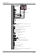
Connection diagram
AC 230 V
X1
X2
X3
X9
X500
X501
M
Heating circuit timer
Timer contact
Functional earth
Fan supply
Gas valve
Heating circuit pump
3 way valve
Heating circuit / DHW
or condensate pump
1)
1)
Heating circuit pump
DHW pump
Function earth ( X900)
has to be connected to burner ground independent from
Flame (ionization probe)
OFF
ON
Summer
Winter
Summer / winter /
OFF / reset
Burner switch
(not at LMU34)
L **) / L1 *)
N **) / L2 *)
N
PE
Room thermostat
Fuse 1
Connector block
(not at LMU34)
N Reset
L Room thermostat input
X401
Flue gas temperature limit thermostat not safety relevant
(NTC or contact)
Temperature switch ( )not safety relevant
PWM fan interface supply GND (not safety relevant)
Fan hall sensor (fan speed)
Output PWM fan control
PWM fan interface supply + (not safety relevant)
Heating circuit temperature sensor
X400
X X
DHW temperature sensor
Outside sensor
DHW flow switch
DHW hall sensor / condensate switch
1)
1)
Heating circuit flow switch primary (hall or contact)
Water pressure switch / bridge (not safety relevant)
X200
PC tool interface (OCI490)
X403
Interface for parameterization IF (OCI425)
X900
Function earth (has to be connected to burner ground independent from X500)
PELV
Fuse
2
X700
Output PWM heating circuit pump contro
PWM heating circuit pump GND
X301
X800
OpenTherm
Heating circuit zone pump / alarm message
1)
Fuse max. T3.15H250
1) Depending on the type of LMU34