
User Manual


12/32
Building Technologies Division CC1N7491en
18.07.2018
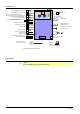
Function (cont´d)
AC 230 V
NTC - 10 k
NTC - 10 k
NTC - 1 k
FE
Limit thermostat (TB) (safety relevant)
Room thermostat (Y-plan compatible)
Heating flow meter primary (hall or contact /
water pressure switch / bridge (not safety relevant)
DHW hall sensor / DHW FlowSwitch *)
or input condensate switch *)
Flue gas temperature limiter
NTC or contact (not safety relevant)
Heating temperature sensor
DHW temperature sensor
Outside sensor
Heating time switch
Reset N (safety relevant)
Ionization probe
(safety relevant)
Mains power supply (main switch and
fuses outside the PCB)
NTC
Power
transformer
OpenTherm room unit
(additional P-settings, etc.)
Interface
PC tool or ACS420 / OCI490
PC tool or ACS425 / OCI425
230V RAC
DC 24 V interface (PELV)
Gas valvel
DC fan
(PWM / HALL)
Heating circuit pump
(not safety relevant)
3 way valve heating / DHW *)
or
condensate pump *)
AC 230 V
AC 230 V
AC 230 V
AC 230 V
HMI
DHW
LED´s
Flame
DHW
DC 7V PWM interface
AC 230 V
AC 230 V
AC 230 V
Potential-free connection
heating circuit zone pump /
alarm message
1
2
3
*) Depending on the type of LMU34
Fault display
Β
Note!
For more details, refer to LMU34 specification!