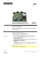
7 Boiler Management Units 491 LMU34... LMU34 are used for premix condensing gas-fired boilers with pneumatic air / gas ratio control and modulating fan. The LMU34 and this Data Sheet are intended for use by OEMs which integrate the BMUs in their products. Use The LMU34… provide all functions required for gas-fired heating boilers in intermittent operation, burner capacity up to 70 kW. Gas modulation takes place by fan speed variation. The LMU34 are designed for residential applications only.
Warning notes To avoid injury to persons, damage to property or the environment, the following warning notes must be observed! Do not open, interfere with or modify the unit! Siemens AG does not assume responsibility for damage resulting from unauthorized interference! ∂ ∂ ∂ ∂ ∂ ∂ ∂ ∂ ∂ ∂ ∂ ∂ ∂ All activities (mounting, installation and service work, etc.
Engineering notes The boiler manufacturer is responsible for correct parameterization of the LMU34. The parameter settings must be in compliance with the relevant standards and directives (e.g.
Installation notes ∂ ∂ ∂ ∂ ∂ ∂ ∂ ∂ ∂ ∂ The LMU34 cannot be operated on isolated networks (with no reference to ground) The high limit thermostat (TB) must be short-circuit proof and adequately secured in its position Install switches, fuses and earthing, in compliance with local regulations Make certain that the maximum permissible current rating of the connection terminals is not exceeded When wiring the unit, ensure that mains voltage and protective extra low-voltage are always strictly separated to wa
Electrical connection of ionization probe or ignition electrode Ionization probe It is important to achieve practically disturbance- and loss-free signal transmission: ∂ Never run the detector cable together with other cables – Line capacitance reduces the magnitude of the flame signal – Use a separate cable ∂ The ionization probe does not offer protection against electrical shock hazard ∂ Isolation resistance - The isolation resistance between ionization probe and ground reduce the quantity of the flame s
Standards and certificates Applied directives: ∂ Low-voltage directive ∂ Gas Appliances Regulation (EU) ∂ Electromagnetic compatibility EMC (immunity) *) 2014/35/EU (EU) 2016/426 2014/30/EU *) The compliance with EMC emission requirements must be checked after the Boiler Management Unit is installed in equipment Compliance with the regulations of the applied directives is verified by the adherence to the following standards / regulations: ∂ Automatic burner control systems for burners and appliances DIN
Disposal notes The unit contains electrical and electronic components and must not be disposed of together with domestic waste. Local and currently valid legislation must be observed. Type Mains voltage Phase (L) / neutral conductor (N) interchangeable Additional potential-free relay output for pump heating circuit / alarm output Integrated DHW relay Interface to OpenTherm Type summary S55405-C305-D... LMU34.210D... AC 230 V ˜ ˜ --- ˜ S55405-C30x-D... LMU34.211D...
Accessories (to be ordered separately) Room unit (depending on the type of LMU34) - Refer to Basic Documentation P2284 Relay PCB ∂ For control a high-efficiency pump via LMU34 ∂ On request ∂ See Data Sheet N7216 Communication interface - Interface for parameterization software ACS425 - See Data Sheet N7613 - Interface for laboratory tool ACS420 PC software - Software tool for laboratory - Software tool for parameterization QAA73... AGU2.005A... OCI425 Article no.: BPZ:OCI425 OCI490...
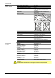
Technical data LMU34… General unit data Mains voltage (rated voltage) Mains frequency Power consumption (with no loads) Degree of protection Safety class Mounting position AC 230 V 50 Hz 10 VA IP00 IP40 or IP54 (to be ensured through mounting) Unit designed for use in equipment of safety class I Vertical (refer to illustration) 7491z06/1016 Dimensions (L x W x D) Weight Unit fuses to IEC 60127 (mains supply) - External side Material Rated impulse voltage category Pollution degree 160 x 127 x 43.
Technical data (cont´d) Flame supervision with ionization probe Connector X800 Ionization current DC switching threshold Possible ionization current Short-circuit current Response time in the event of loss of flame Safety time «TSA» Repetition 0.45 µA (typically) Max. 11 µA Max. 51 µA <1 s Connection Type PELV Stocko: MKS1852-6-0-202 2 poles, coded Connections are interchangeable and short-circuit-proof short-circuit might lead to activation of special LMU34… functions Lumberg: 2.
Functions ∂ ∂ ∂ ∂ ∂ ∂ ∂ ∂ ∂ ∂ ∂ ∂ ∂ ∂ ∂ ∂ ∂ ∂ ∂ ∂ ∂ ∂ ∂ ∂ ∂ ∂ ∂ General functions Modulating control in both central heating (CH) and domestic hot water (DHW) mode PID control of the heating water temperature PID control of the DHW temperature (DHW outlet temperature) NTC temperature sensor on central heating flow pipe NTC temperature sensor on instantaneous DHW line or storage tank Connection facility for a CH programmer / timer Connection facility for a non-safety-related flow switch (CH) or water pressu
Function (cont´d) Limit thermostat (TB) (safety relevant) AC 230 V Room thermostat (Y-plan compatible) HMI LED´s Heating flow meter primary (hall or contact / water pressure switch / bridge (not safety relevant) Gas valvel AC 230 V Flame DC 24 V interface (PELV) DHW DHW hall sensor / DHW FlowSwitch *) or input condensate switch *) Flue gas temperature limiter NTC or contact (not safety relevant) NTC DHW DC fan (PWM / HALL) AC 230 V NTC - 10 k Heating temperature sensor AC 230 V NTC - 10 k DH
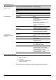
Cause Error 10 Error outside sensor 1 Short-circuit of outside temperature sensor Error 20 Error boiler temperature sensor 1 1 Short-circuit of boiler temperature sensor Error 20 Error boiler temperature sensor 1 2 Open-circuit of boiler temperature sensor Error 28 Error flue gas temperature sensor 1 Short-circuit of NTC flue gas sensor Error 28 Error flue gas temperature sensor 2 Open-circuit of NTC flue gas sensor Error 50 Error DHW temperature sensor / thermostat 1 1 Short-circuit
QAA73 display of error code Meaning of QAA73 text display Internal diagnostics code Error code list (cont’d) Cause Error 160 Fan speed threshold not reached 20 Under run of minimum fan speed threshold, wrong air supply, retry Error 160 Fan speed threshold not reached 21 5 times under run of minimum fan speed threshold, wrong air supply, retry after 2 hour Error 160 Fan speed threshold not reached 22 Fan speed on standstill in standby not reached Error 160 Fan speed threshold not reached 2
Parameterization Parameterization by QAA73 (service tool): Users Features Parameter types Parameter levels Connection of QAA73 Installer / service Changing various LMU34 parameters Non-safety-related Heating engineer To LMU34 The LMU34 can be configured for different applications by setting parameters via the QAA73. To make this procedure easy for the installer, 16 sets of parameters have been defined, every set consisting of 9 parameters, and one set for each application.
Parameterization (cont´d) Parameters and service data that can be edited and viewed in a direct way via the QAA73: OT OT text Function Access Range Unit 504 TkSmax Max. CH temperature read / write c8_TKSollMin...90 °C 516 THG Summer / winter changeover threshold read / write 10...30 °C 532 Sth1 Slope CH 1 read / write 2...33 --- 534 DtR1 Nominal room adjustment read / write -4.5...4.5 K 536 NhzMax Max. fan speed in CH mode read / write 0...6350 rpm No. 541 PhzMax Max.
OT OT text Function Access Range Unit 731 Stralba4 Fourth previous Albatros fault code read --- --- 732 Stralba5 Fifth previous Albatros fault code read --- --- No. 733 Stralba_akt Actual Albatros fault code read --- --- 750 Status_Eingang1 Status input signals LMU34… read --- --- 752 Status_Ausgang1 Status output signals LMU34… read --- --- Β Note! Additional parameters via ACS425! 17/32 Building Technologies Division CC1N7491en 18.07.
Display of additional service data Using the CH potentiometer, several internal parameters can be displayed. For activation of this function, the CH potentiometer must be moved from the starting position to the «Display» area, then out of it and back into it again – all within one second. The function will be active 2 seconds later. The Heating circuit potentiometer can then be used again to set the heating setpoint. It is not necessary to keep it in the «Display» position.
Addendum: Applications CH and instantaneous DHW heating with 3-port valve: CH and DHW storage tank with heating circuit pump and 3-port valve: Room thermostat Room thermostat HC1 HC1 Heat circuit 1 LMU34... Heat circuit 1 Room thermostat Room thermostat LMU34...
Addendum: Applications (cont´d) Heating zone with weather-compensated heating curve for CH setpoint, with or without room temperature influence: 20 °C Remote control Motor 3 way valve Outside temperature sensor OTS Outside temperature senstor Boiler 1 Primary heat exchanger 7491a09e/1116 Multizone system, controlled via room thermostat: Room thermostat Room thermostat Room thermostat Motor 3 way valve LMU34...
Addendum: Applications (cont´d) Multizone system, controlled via room thermostat, with outside sensor: OTS Outside temperature sensor Outside temperature sensor Room thermostat Room thermostat Room thermostat Motor 3 way valve LMU34...
Connection diagram AC 230 V L **) / L1 *) X1 Burner switch (not at LMU34) OFF ON N **) / L2 *) X2 Connector block (not at LMU34) Fuse 1 N Fuse 2 Functional earth PE Summer Fan supply Room thermostat Winter Summer / winter / OFF / reset X3 Gas valve DHW pump Heating circuit pump Heating circuit pump 3 way valve 1) Heating circuit / DHW or condensate pump 1) N Reset L Room thermostat input X9 M Heating circuit timer Timer contact X301 Heating circuit zone pump / alarm message 1) Fuse max
Connection diagram (cont’d) Caution! Connection of X500 with X900 – in each case without separate connection to burner ground and protective – with fault, there is a risk of electric shock hazard! *) Applications L1 / L2 are only permitted in EC countries **) Standard application with L / N for EC Attention! The mains power supply of PWM-controlled high-efficiency pumps (heating circuit pump) must not be connected to terminal X3 pin 3 / pin 4. 23/32 Building Technologies Division CC1N7491en 18.07.
Connectors list LMU34. No. Connector type X1 Molex 2599 2 poles X2 X3 Pin code print on PCB Description LMU34.2… HT: Mains supply connector AC 230 V, 50 Hz 1 LMU34.2…: Mains supply L / L1 2 LMU34.2…: Mains supply N / L2 Stelvio CFM / 5 A ˜ ˜ Cable length ′ 1 m HT: 1 Functional earth (not for protection purposes) 2 Ignition ¹) supply N 3 Mains supply L for PWM fan 4 Mains supply L for PWM fan 5 Ignition ¹) supply L Molex 2599 9 poles Half wave rectified AC max. 3 VA AC 230 V max.
Connectors list (cont´d) No. Connector type X9 Molex 2599 4 poles X200 X301 ) 4 Pin code print on PCB Description LMU34.
Connectors list (cont´d) No. X400 Connector type Pin code print on Description LMU34.2 PCB Lumberg MSF 9 poles PELV: Cable length ′ 1 m 1 DHW temperature sensor NTC 10 kς at 25 °C beta = 3977 DC 5 V 2 Outside temperature sensor NTC 1 kς at 25 °C beta = 3528 cable length ′ 40 m Open-circuit condition: Vout = DC 7.5 V Closed-circuit condition: Iout < 1 mA Uin < 0.5 V 3 DHW Hall sensor / DHW flow switch IN 4 DHW temperature sensor NTC 10 kς at 25 °C beta = 3977 max.
Connectors list (cont´d) No. Connector type X401 Lumberg MSF 10 poles Pin code print on PCB LMU34.2 PELV: Cable length ′ 1 m Flue gas temperature NTC ²) or thermostat contact NTC 20 K at 25 °C beta = 3970 DC 5 V < 2 mA 2 Flue gas temperature NTC ²) or thermostat contact NTC 20 K at 25 °C beta = 3970 DC 5 V < 2 mA 3 High limit thermostat (TB) Half wave rectified RAC 24 V I = 2.5...5 mA 4 High limit thermostat (TB) Half wave rectified RAC 24 V I = 2.5...
Connectors list (cont´d) No. Connector type X700 Lumberg 3850 2 poles Pin code print on PCB Description PELV: PWM heating circuit pump LMU34.2 Cable length ′1 m Output voltage at Iout = 1 mA: DC 7 V ±5%, Ri = 100 R Output voltage at Iout = 10 mA: DC 6,2 V ±5%, Ri = 100 R Output current (shortcircuit proof): Max. 10 mA PWM frequency: 300 Hz 1 PWM + 2 GND 1/2 PELV: OpenTherm V2.
Dimensions Dimensions in mm 7491m13e/1116 90 1.55 7 25 34.5 LMU34 52 75 21.52 85.25 77.94 80.24 17.19 5 94 35.54 110.06 117 127 17.5 24.95 5 62.5 87.5 160 *) Depending on the type of LMU34 29/32 Building Technologies Division CC1N7491en 18.07.
Design guide line Dimensions in mm Component side LMU34… 90 52 .2 +0 A M5:1 A 17 +0.1 5 93.2 +0.1 94 2. 1 1.2 5.5 102.5 +0.1 5 6. 4.5 +0.1 1.5 +0.2 1 5.3 Zero point Β 7491m14e/1116 Note! Holes Ø6.5 are not plated-through. 30/32 Building Technologies Division CC1N7491en 18.07.
Design guide line (cont’d) Dimensions in mm 6x) 9( Component side LMU34 (cont’d) Slope from 27 to 54 Total height max. 54 33 62 77 65 Zero point Height max. 34 7491m17e/1116 13 Total height max. 27 Area free of components and PCB track 31/32 Building Technologies Division CC1N7491en 18.07.
Design guide line (cont´d) Dimensions in mm 55 50 Soldering side LMU34… 56 3.5 52 9 (6x ) 34 3 (2x) 39 39 22 (2x) Height max. 5 94 44 (2x) 52 Height max. 7 Height max. 11 4 (4x) 3.5 44 28 44 Height max. 16 3.5 14 Height max. 5 7491m16e/1116 4 (2x) 50 55 Zero point Area free of components 32/32 Building Technologies Division 2018 Siemens AG Building Technologies, Berliner Ring 23, D-76437 Rastatt Subject to change! CC1N7491en 18.07.