
User Manual

28/33
Building Technologies CC1N7491.1en
03.04.2018
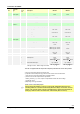
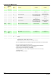
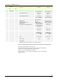
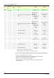
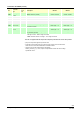
Connectors list LMU34 (cont´d)
No.
Connector
type
Pin code
print on
PCB
Description LMU34.2 LMU34.3
X401
Lumberg
MSF 10 poles
PELV: Cable length ′ 1 m Cable length ′ 1 m
1
Flue gas temperature NTC ²) or thermostat
contact
LMU34 type "A":
NTC 10 kς at 25 °C
Beta = 3977
LMU34 type "B":
NTC 20 K at 25 °C
beta = 3970
DC 5 V
< 2 mA
NTC 20 k ς at 25 °C
beta = 3970
DC 5 V
< 2 mA
2
Flue gas temperature NTC ²) or thermostat
contact
LMU34 type "A":
NTC 10 kς at 25 °C
Beta = 3977
LMU34 type "B":
NTC 20 K at 25 °C
beta = 3970
DC 5 V
< 2 mA
NTC 20 k ς at 25 °C
beta = 3970
DC 5 V
< 2 mA
3 High limit thermostat (TB)
Half wave rectified
RAC 24 V
I = 2.5...5 mA
Half wave rectified
AC 24 V
I = 2.5...5 mA
4 High limit thermostat (TB)
Half wave rectified
RAC 24 V
I = 2.5...5 mA
Half wave rectified
AC 24 V
I = 2.5...5 mA
5
Fan interface supply GND ¹) ³)
GND GND
6
Fan hall sensor (fan speed) IN (non safety)
¹) ³)
2 rectangular pulses per
revolution
duty ratio 1:1 +/-5 %
2 rectangular pulses per
revolution
duty ratio 1:1 +/-5 %
7
PWM fan control output (non safety) ¹) ³)
4,800 Hz 4,800 Hz
8
PWM fan interface supply + ¹) ³)
DC 30 V DC 30 V
9 Boiler temperature sensor
NTC 10 kς at 25 °C
beta = 3977
DC 5 V
NTC 10 kς at 25 °C
beta = 3977
DC 5 V
10 Boiler temperature sensor
NTC 10 kς at 25 °C
beta = 3977
DC 5 V
NTC 10 kς at 25 °C
beta = 3977
DC 5 V
HT: High Tension – Mains voltage connection
PELV: Protective Extra Low Voltage – Low voltage connection
The unit is supplied with the temperature setpoint potentiometer in the OFF position.
¹) Only use components approved by Siemens AG!
²) A special conversion list (hard copy) must be used to retrieve correct measurement
values and to set correct threshold values to related functions
³) The fan must meet the requirements of specification
LMU5x_TrafoFan_en_V1.2.doc, chapter 3 “Specification for fans with mains voltage
operated DC motor”