7 Boiler Management Units 491 LMU34.xxxAxxx LMU34.xxxBxxx LMU34 are used for premix condensing gas-fired boilers with pneumatic air / gas ratio control and modulating fan. The LMU34 and this Data Sheet are intended for use by OEMs which integrate the BMUs in their products. Use The LMU34 provide all functions required for gas-fired boilers in intermittent operation, burner capacity up to 70 kW. Gas modulation takes place by fan speed variation. The LMU34 are designed for residential applications only.
Warning notes To avoid injury to persons, damage to property or the environment, the following warning notes must be observed! Do not open, interfere with or modify the unit! Siemens AG does not assume responsibility for damage resulting from unauthorized interference! ∂ ∂ ∂ ∂ ∂ ∂ ∂ ∂ ∂ ∂ ∂ ∂ ∂ All activities (mounting, installation and service work, etc.
Application notes Notes on integrating the LMU34 (boiler for gaseous fuels type C, rated capacity ′70 kW): ∂ The impact of continuous control of the ignition equipment caused by an internal failure of one of the burner control components in connection with an earth fault of one of the connecting wires of the ignition equipment must be assessed depending on the application ∂ High limit thermostat function Signals from the potential-free contact at terminals X401: X401 pin 3 / X401 pin 4 will be further handl
Installation notes ∂ ∂ ∂ ∂ ∂ ∂ ∂ ∂ ∂ ∂ ∂ The LMU34 cannot be operated on isolated networks (with no reference to ground) The high limit thermostat (TB) must be short-circuit proof and adequately secured in its position Do not mix up live and neutral conductors (only LMU34.
Electrical connection of ionization probe or ignition electrode Ionization probe It is important to achieve practically disturbance- and loss-free signal transmission: ∂ Never run the detector cable together with other cables – Line capacitance reduces the magnitude of the flame signal – Use a separate cable ∂ The ionization probe does not offer protection against electrical shock hazard ∂ Isolation resistance - The isolation resistance between ionization probe and ground reduce the quantity of the flame s
Standards and certificates Applied directives: ∂ Low-voltage directive ∂ Gas Appliances Regulation ∂ Electromagnetic compatibility EMC (immunity) *) 2014/35/EC EU/2016/426 2014/30/EC *) The compliance with EMC emission requirements must be checked after the Boiler Management Unit is installed in equipment Compliance with the regulations of the applied directives is verified by the adherence to the following standards / regulations: ∂ Automatic burner control systems for burners and appliancDIN EN 298 es
Life cycle LMU34 boiler management unit have a designed lifetime* of 250,000 burner startup cycles which, under normal operating conditions in heating mode, correspond to approx. 10 years of usage (starting from the production date given on the type field). This lifetime is based on the endurance tests in the standard EN 298. A summary of the conditions has been published by the European Control Manufacturers Association (Afecor) (www.afecor.org).
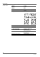
Integrated DHW relay LMU34.210Axxx AC 230 V ˜ ˜ ˜ BPZ:LMU34.210Bxxx LMU34.210Bxxx AC 230 V ˜ ˜ ˜ BPZ:LMU34.215Bxxx LMU34.215Bxxx AC 230 V ˜ BPZ:LMU34.216Bxxx LMU34.216Bxxx AC 230 V ˜ BPZ:LMU34.220Bxxx LMU34.220Bxxx AC 230 V ˜ BPZ:LMU34.300Axxx LMU34.300Axxx BPZ:LMU34.300Bxxx BPZ:LMU34.301Bxxx CSA approval Interface to AGU2.002 (OpenTherm / pump module) BPZ:LMU34.210Axxx Mains voltage AquaBooster with additional DHW sensor 2 Type DHW relay as a condensate pump Article no.
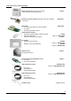
Accessories (to be ordered separately) Room unit (depending on the type of LMU34) - Refer to Basic Documentation P2284 QAA73... Interface and pump module (depending on the type of LMU34) - For QAA73 AGU2.002A… Relay PCB ∂ For control a high-efficiency pump via LMU34 ∂ On request ∂ See Data Sheet N7216 / N7217 AGU2.005A...
Technical data LMU34 General unit data Mains voltage (rated voltage) - LMU34.2 - LMU34.3 Mains frequency - LMU34.2 - LMU34.3 Power consumption (with no loads) Safety class Mounting position AC 230 V AC 120 V 50 Hz 60 Hz 10 VA Unit designed for use in equipment of safety class I Vertical (refer to illustration) 7491z06/1204 Dimensions (L x W x D) Weight Unit fuses to 60127 (mains supply) ∂ LMU34.2 (external side) ∂ LMU34.
Technical data (cont´d) Environmental conditions Storage Climatic conditions Mechanical conditions Temperature range Humidity Transport Climatic conditions Mechanical conditions Temperature range Humidity Operation Climatic conditions Mechanical conditions Temperature range Humidity Installation altitude DIN EN 60721-3-1 Class 1K3 Class 1M2 -20...+60 °C <90 % r.h. DIN EN 60721-3-2 Class 2K2 Class 2M2 -20...+60 °C <90 % r.h. DIN EN 60721-3-3 Class 3K3 Class 3M2 -20...+60 °C <90 % r.h. Max.
Technical data (cont´d) AGU2.002 General unit data Connector X1 Type Loads Function Connector X2 Type Loads Function Connector X3 Type Loads Assignment Function PELV Siemens AG system-internal connection cable is supplied together with AGU2.002, 5 poles, coded Connected to LMU34 (PELV) Siemens AG system-internal connection Interface for LMU34 PELV Stocko: MKS1852-6-0-202 2 poles, coded AGU2.
External system components External system components are devices such as ∂ Ignition equipment ∂ Fan ∂ Gas valve ∂ Flow switch Hall sensor DHW ∂ Heating circuit pump The external system components used must be approved by Siemens AG! Functions ∂ ∂ ∂ ∂ ∂ ∂ ∂ ∂ ∂ ∂ ∂ ∂ ∂ ∂ ∂ ∂ ∂ ∂ ∂ ∂ ∂ ∂ ∂ ∂ ∂ ∂ ∂ Modulating control in both central heating (CH) and domestic hot water (DHW) mode PID control of the boiler temperature PID control of the DHW temperature (DHW outlet temperature) (depending on the type of LMU34)
Functions (cont'd) General functions Function modes: The general function modes are: ∂ Standby ∂ Frost protection ∂ Combi comfort ∂ Central heating ∂ DHW (combi or storage tank) (depending on the type of LMU34) ∂ Chimney sweep function ∂ Controller stop function ∂ Anomaly Operating modes (OFF, summer, winter, remote and reset): The following operating modes can be selected by means of the external rotary switch (see chapter Connection diagram): ∂ Summer ∂ OFF ∂ Winter ∂ Reset (monostable position) Fault d
Functions (cont'd) Temperature limiter (TB) (security related) AC120/230V Room thermostat (compatible with Y-Plan) *) HMI LED´s Flow monitor heating primary (hall or contact / water pressure switch / bridge) (not security related) DHW hall sensor / DHW flow switch *) or input condensate switch *) NTC-10 K or DHW temperature sensor 2 *) Flue gas temperature limiter NTC or contact (not security related) NTC Gas valve *) AC120/230V Flame DC 24 V interface (PELV) DHW DHW AC120/230V NTC - 10 k Temper
Meaning of QAA73 text display Internal diagnostics code on LMU34 type) QAA73 display of error code (depending Error code list Cause Error 10 Error outside sensor 1 Short-circuit of outside temperature sensor Error 20 Error boiler temperature sensor 1 1 Short-circuit of boiler temperature sensor Error 20 Error boiler temperature sensor 1 2 Open-circuit of boiler temperature sensor Error 28 Error flue gas temperature sensor 1 Short-circuit of NTC flue gas sensor Error 28 Error flue gas
Meaning of QAA73 text display Internal diagnostics code on LMU34 type) QAA73 display of error code (depending Error code list (cont’d) Cause Error 156 Error supply voltage 20 Undervoltage fault (burner control start prevention) Error 156 Error supply voltage 21 Undervoltage fault (indication, no start prevention) Error 156 Error supply voltage 22 Over Voltage Fault (indication, no start prevention) Error 158 Error condensate 0 Condensate pump continuous operation Error 160 Fan speed t
Parameterization Parameterization by QAA73 (service tool) (depending on the type of LMU34): Users Features Parameter types Parameter levels Connection of QAA73 Installer / service Changing various LMU34 parameters Non-safety-related Heating engineer To LMU34 via AGU2.002 The LMU34 can be configured for different applications by setting parameters via the QAA73.
Parameterization (cont´d) Parameters and service data (depending on the LMU34 type) can be edited and viewed in a direct way via the QAA73: No. OT text Function Access Range Unit 1 TkSmax Max. boiler temperature read / write c8_TKSollMin...90 °C 2 THG Summer / winter changeover threshold read / write 10...30 °C 3 Sth1 Slope CH 1 read / write 2...33 --- 4 DtR1 Nominal room adjustment read / write -4.5...4.5 K 5 NhzMax Max. fan speed in CH mode read / write 0...
Display of additional service data Using the CH potentiometer (heating), several internal parameter values can be displayed. For activation of this function, the CH potentiometer must be moved from the starting position to the «Display» area, then out of it and back into it again – all within one second. The function will be active 2 seconds later. The Heating circuit potentiometer can then be used again to set the heating setpoint. While operating the CH potentiometer, the CH setpoint will be displayed.
Addendum: Applications CH and instantaneous DHW heating with 3-port valve: CH and DHW storage tank with heating circuit pump and 3-port valve: Room thermostat Room thermostat HC1 HC1 Heat circuit 1 LMU34... Heat circuit 1 Room thermostat Room thermostat LMU34...
Addendum: Applications (cont´d) Heating zone with weather-compensated heating curve for CH setpoint, with or without room temperature influence: CH + DHW Potentiometers without function QAA73 Remote control Remote Motor 3 way valve control 20 °C LMU34... Q1 DHW start Outside temperature sensor CH setpoint DHW setpoint CH timer DHW timer OpenTherm AGU2.
Addendum: Applications (cont´d) Multizone system, controlled via room thermostat, with outside sensor: OTS Outside temperature sensor Outside temperature sensor Room thermostat Room thermostat Room thermostat Motor 3 way valve LMU34...
Connection diagram Burner switch (not at LMU34) AC 230 V L **) / L1 *) X1 OFF ON N **) / L2 *) X2 Connector block (not at LMU34) Fuse 1 N Fuse 2 Functional earth PE Summer Winter Summer / winter / OFF / reset Fan supply X3 Gas valve Room thermostat DHW pump Heating circuit pump Heating circuit pump 3 way valve 1) Heating circuit / DHW or condensate pump 1) N Reset L Room thermostat input X9 M Heating circuit timer Timer contact X500 X501 Function earth (has to be connected to burner gr
Connectors list LMU34 No. Connector type X1 Molex 2599 2 poles X2 X3 Pin code print on PCB Description LMU34.2 LMU34.3 HT: Mains supply connector AC 230 V, 50 Hz AC 120 V, 60 Hz 1 LMU34.2: Mains supply L / L1 ˜ --- 1 LMU34.3: Mains supply L --- ˜ 2 LMU34.2: Mains supply N / L2 ˜ --- 2 LMU34.3: Mains supply N --- ˜ Cable length ′ 1 m Cable length ′ 1 m Half wave rectified AC max. 3 VA Half wave rectified AC max. 3 VA AC 230 V max. 160 VA AC 230 V max.
Connectors list LMU34 (cont´d) No. Connector type X9 Molex 2599 4 poles Pin code print on PCB 4) LMU34.
Connectors list LMU34 (cont´d) No. X400 Connector type Pin code print on Description LMU34.2 LMU34.3 PELV: Cable length ′ 1 m Cable length ′ 1 m 1 DHW temperature sensor NTC 10 kς at 25 °C beta = 3977 DC 5 V NTC 10 kς at 25 °C beta = 3977 DC 5 V 2 Outside temperature sensor NTC 1 kς at 25 °C beta = 3528 cable length ′ 40 m NTC 1 kς at 25 °C beta = 3528 cable lengths ′ 40 m PCB Lumberg MSF 9 poles LMU34 type "A": NTC 10 kς at 25 °C Open-circuit condition: Vout = DC 7.
Connectors list LMU34 (cont´d) No. Connector type X401 Lumberg MSF 10 poles Pin code print on PCB Description PELV: LMU34.2 LMU34.
Connectors list LMU34 (cont´d) No. Connector type X403 Lumberg 3850 4 poles Pin code print on PCB Description PELV: PARA-IFC (OCI425) 1 Internal 2 Internal 3 Internal 4 Internal HT: Functional earth (burner ground) (not for protection purposes) LMU34.2 LMU34.3 OCI425 / ACS425 OCI425 / ACS425 Cable length ′ 1 m Cable length ′ 1 m X500 Tabs 6.3 mm X501 VT tabs 4.8 mm HT: Flame (ionization probe) < AC 100 V cable length ′ 1 m < AC 100 V cable length ′ 1 m X900 Tabs 6.
Dimensions Dimensions in mm 1,55 7 34,5 LMU34 90 52 75 11 24,95 40 X401 35 17,5 X400 X300 *) X200 X900 21,52 20 65 80,18 85,25 94 31 17,53 107,82 127 117 32,94 2 4, X501 x (6 X500 5 ) 5 87,5 62,5 160 *) Depending on the type of LMU34 AGU2.002 16,6 (depending on the type of LMU34) 40 5 X1 35 7491m01/0406 8 X3 45 X2 7 11 10 5 9 25 20 51 Terminal X2 X3 Pin 7 8 9 10 11 Function OpenTherm 30/33 Building Technologies CC1N7491.1en 03.04.
Dimensions (cont´d) Dimensions in mm 15,9 Mounting position for AGU2.002 on the LMU34 X900 X400 X401 45 X200 X300 *) 6 60 51 X501 X500 *) Depending on the type of LMU34 31/33 Building Technologies CC1N7491.1en 03.04.
Design guide line Dimensions in mm Component side LMU34 9 (6 x) ) 4x 6( 45 Inclined plane from 27 up to 54 Total height max. 54 (with AGU2.002... mounted) 33 62 60 77 65 Zero point Total height max. 34 7491m03e/1006 13 Total height (with AGU2.002... mounted) max. 27 Area free of components and PCB track With AGU2.002... mounted total height of LMU34... circuit printed board max. 15 51 45 6 60 M1:2 Zero point 7491m05e/1006 32/33 Building Technologies CC1N7491.1en 03.04.
Design guide line (cont´d) Dimensions in mm 55 50 Soldering side LMU34 34 56 3 (2 x) Total height max. 5 22 (2 x) x) 52 total height max. 7 Total height max. 16 44 44 3,5 4 (4 x) 94 44 (2 x) total height max. 11 6 (4 39 x) 39 9 (6 3,5 52 3,5 14 28 Total height max. 5 7491m04e/1006 4 (2 x) 50 Zero point 55 Area free of components and PCB track 2018 Siemens AG Building Technologies, Berliner Ring 23, D-76437 Rastatt Subject to change! Building Technologies 33/33 CC1N7491.